Fuel Pump Relay: How to Test a Suspected Fault
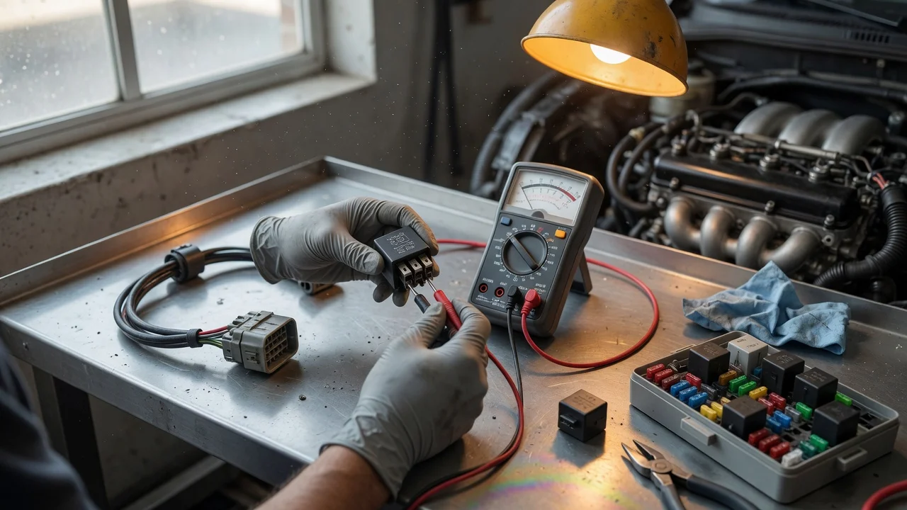
To test a suspected fuel pump relay fault, first confirm how your vehicle controls the fuel pump. Then use its wiring diagram and test procedure to check the relay’s power supply, control circuit and switched output under the specified operating conditions. A click, a silent pump or a starting problem alone does not establish that the relay is faulty.
Confirm which component you are testing
In a conventional arrangement, the fuel pump relay is an electrically operated switch that controls power to the pump circuit. Depending on the model year, engine, market and configuration, the vehicle may instead use an integrated relay, a fuel pump control module or another electronic switching arrangement. A control module is not interchangeable with a removable relay.
Use service information for the exact vehicle to identify the component, its location, the associated fuse and the circuit connections. No vehicle details or technical documentation were supplied here, so relay location, terminal assignments, expected readings and activation timing cannot be specified reliably.
Prepare before testing
Have the applicable wiring diagram and diagnostic procedure, a suitable digital multimeter and the test leads or adapters required by that procedure. Some systems also require a compatible diagnostic scan tool to request pump operation or inspect control information. Confirm the required ignition, cranking or commanded-operation state before interpreting any reading.
Secure the vehicle against movement and keep clear of parts that may move if the engine starts. Do not open fuel lines for an electrical relay check. Stop if you find leaking fuel, strong fuel vapors, melted wiring or a damaged relay socket. Avoid sparks and improvised jumper wires; bridging unidentified terminals can damage wiring or electronic controls.
Check the circuit in order
1) Establish the symptom. Record whether the engine cranks without starting, stalls or shows another problem, and when it happens. These observations guide testing but do not identify the relay as the cause. Do not assume that a pump must run continuously whenever the ignition is on.
2) Inspect the identified circuit. Follow the prescribed shutdown procedure before removing components. Check the relevant fuse, relay and socket for damage, corrosion or loose connections. A blown fuse needs investigation; replacing the relay does not explain why the fuse opened.
3) Verify the power supply. Following the wiring diagram, check whether the relay’s supply circuit meets the specified test criteria. If supply is missing, investigate the fuse, connections and upstream wiring before condemning the relay. A voltage reading without the required load may leave a poor connection unresolved.
4) Verify the control circuit. Check for the required activation signal and electrical return path under the documented operating conditions. Control arrangements vary, so do not assume which terminal receives power or ground. If activation is absent, the next checks concern the control circuit and the conditions needed to enable the pump.
5) Check the switched output. With the relay correctly activated, compare its output with the specified criteria, including any required test under load. Correct supply and control with an output that fails the prescribed test support a switching-path fault. Check socket connections as well as the relay before deciding which component needs repair.
6) Follow the circuit downstream if output is correct. Verify power and ground at the pump using the vehicle’s procedure. Correct relay output does not prove that power reaches the pump, that its ground is sound or that the pump delivers the required fuel pressure. Fuel-pressure testing is a separate task requiring the appropriate procedure and equipment.
Interpret clicks, swaps and fault codes carefully
An audible click from a conventional relay indicates mechanical movement, but it does not prove that the contacts carry the required current. No click may reflect a failed relay, missing control or missing power. Electrical checks distinguish these possibilities more reliably than sound alone.
A substitution test is appropriate only if service information permits it and the replacement relay is confirmed compatible. Matching shape is insufficient. If substitution changes the symptom, the original relay becomes suspect, but disturbing a poor socket connection can also change the result.
A diagnostic trouble code identifies a condition detected by a control system; it is not proof that the named component needs replacement. Check the code definition, enabling conditions and diagnostic steps for the exact vehicle. No code or vehicle information was supplied, so no code-specific conclusion can be made.
Confirm the repair
After correcting the confirmed fault, restore all connections and covers, then repeat the relevant electrical checks and verify operation under the conditions that produced the symptom. One successful start does not establish that an intermittent problem is resolved. If the required circuit information, equipment or safe access is unavailable, have a qualified technician complete the diagnosis.