Agility Trailer Brake Controller: Manual and Wiring
Direct Answer and Scope
The Agility trailer brake controller is a proportional electric brake controller designed to apply trailer brakes in proportion to the tow vehicle's deceleration. It uses an internal inertia sensor rather than a timed delay. The main qualification is that specific wiring colors and manual steps vary by the controller's production revision and by the tow vehicle's brake light and battery feed circuits. Installers should use the printed manual included with the specific unit, because pigtail harnesses are not universal across all Agility variants.
How the Proportional System Works
A proportional controller measures how quickly the tow vehicle is slowing and sends a matching voltage to the trailer brakes. At a gradual stop, the trailer receives light braking. During hard braking, the controller increases output. This differs from time-delay controllers, which apply a preset amount of braking after a delay regardless of actual deceleration. The Agility's internal sensor must be mounted securely and aligned according to the manual, usually with the unit level or angled within the specified range.
Wiring Overview
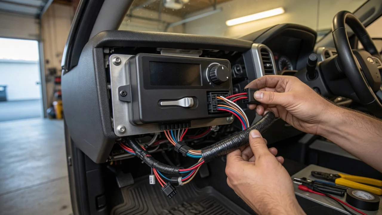
The Agility controller typically requires four connections: a 12-volt battery feed through a self-resetting circuit breaker, a ground wire, a brake switch signal from the tow vehicle, and an output wire to the trailer brake circuit at the trailer connector. The brake switch input tells the controller when the tow vehicle's brake pedal is pressed. The manual brake lever can also activate the trailer brakes independently of the vehicle brake pedal.
Common wiring function | Typical wire role | Notes; 12V power input | Battery feed | Protected by a circuit breaker near the battery; Ground | Chassis or battery negative | Poor ground causes intermittent output; Brake signal | Cold side of brake pedal switch | Active only when brakes are applied; Brake output | Blue wire at trailer plug | Feeds electric brake magnets
Do not rely on generic color codes. A wiring diagram in the Agility manual identifies the harness wire positions for the specific plug style. On some models the harness is a plug-in pigtail; on others the wires terminate in a rectangular connector that mates with a vehicle-specific adapter.
Installation Sequence
Disconnect the tow vehicle battery negative terminal before splicing or connecting wires; Mount the controller bracket within reach and level, then secure the controller; Route the harness away from sharp edges, pedals, and airbag zones; Connect ground and battery feed through the circuit breaker; Connect the brake signal wire to the switch side that has voltage only when the pedal is pressed; Connect the output wire to the trailer brake pin; Reconnect battery and test the manual lever before towing.
Initial Setup and Adjustment
After installation, set the power adjustment to a low starting point. Drive on a flat, low-traffic surface at about 20 mph and apply the trailer brakes with the manual lever. Increase the setting gradually until the trailer brakes are felt but do not lock the wheels. The manual for the specific Agility model describes whether adjustment is done by a rotary control, push buttons, or a slide control.
Repeat the test with the tow vehicle brake pedal rather than the manual lever. Because the system is proportional, the trailer should slow smoothly with the vehicle rather than surging or tugging. A loaded trailer usually needs a higher power setting than an unloaded trailer.
Manual Retrieval and Documentation
For model-specific steps, the printed Agility manual is the authoritative source. It includes the calibration angle, diagnostic blink codes, and the exact harness pinout. Do not substitute a wiring diagram from a different controller simply because the plug fits. If the original manual is lost, the manufacturer may offer a digital copy through official owner-support channels, but no link or address can be supplied here.
Known Diagnostic Indicators
Agility controllers may show status using an LED or display. A common fault indication is no output from the manual lever, which usually points to missing battery feed, a blown circuit breaker, a poor ground, or no trailer connection. Another issue is braking only from the manual lever but not from the pedal, which typically points to the brake signal wire connection. Refer to the manual's blink or message definitions before replacing the unit.
Practical Limitations
The Agility is intended for trailers with electric brakes. It is not a substitute for surge brakes or electric-over-hydraulic systems unless the trailer is configured for an electric brake output. Some tow vehicles have an integrated trailer brake controller, which does not require the Agility. Check the vehicle's factory towing package before adding an aftermarket controller.
This guide is based on documented controller function and general installation practice. It does not imply hands-on testing of a specific Agility sample. Material gaps remain for exact wire colors and calibration angles across production revisions, so the specific manual should always govern the final installation.