What Is Motor Field Weakening? How EV Motors Reach High Speed
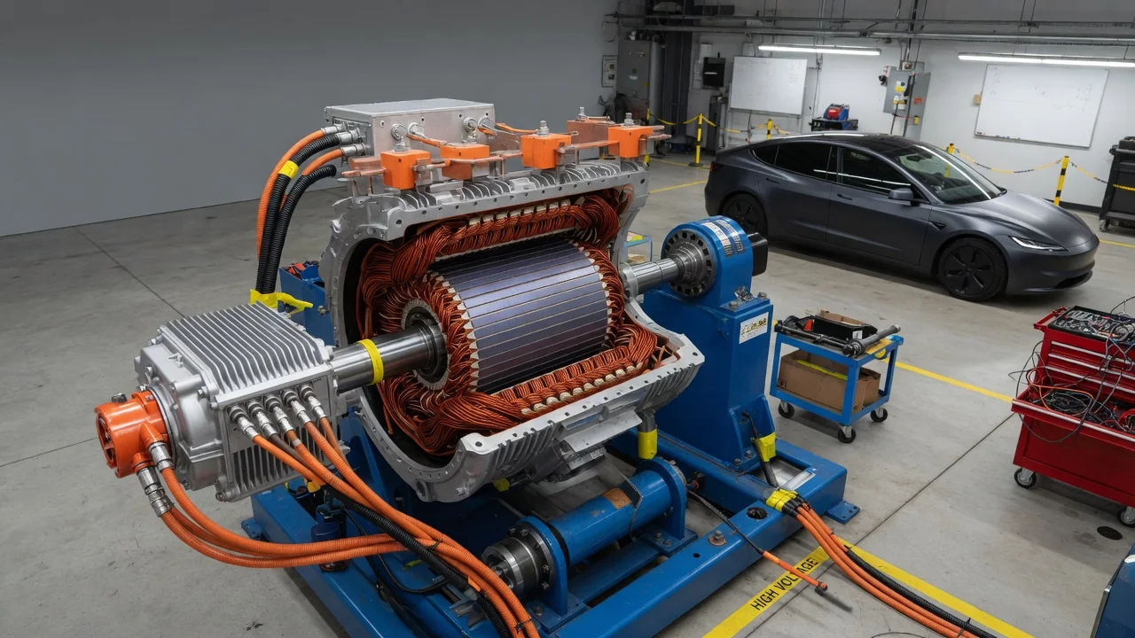
Motor field weakening is a control technique that lets an electric motor spin faster than its voltage limit would otherwise allow. In an electric vehicle, once road speed passes a certain point, the inverter deliberately reduces the effective magnetic field inside the motor. The result is a wider usable speed range from a single gear ratio, at the cost of reduced torque. EV motor field weakening explains why electric cars feel strongest from a standstill and gradually ease off at highway speeds.
High-speed operation
Every spinning motor also acts as a generator. As the rotor turns, its magnetic field sweeps past the stator windings and induces a voltage called back electromotive force, or back-EMF. Back-EMF rises roughly in proportion to rotor speed multiplied by the strength of the magnetic flux linking the windings. To push current into the motor, the inverter must apply a voltage higher than this back-EMF. The highest voltage it can produce is set by the DC voltage of the high-voltage battery.
At some rotor speed, often called base speed, back-EMF approaches the maximum voltage the inverter can deliver. Without intervention, current would fall off sharply, torque would fall with it, and the motor would hit a practical speed ceiling. Field weakening raises that ceiling. Reducing the effective flux lowers back-EMF at a given speed, which restores voltage headroom so the inverter can keep controlling current. The motor can then keep accelerating well beyond base speed. How far it can go depends on motor design. Some machines tolerate a wide field-weakening range, while others have a narrower usable band before efficiency or stability suffers.
Torque change
Below base speed, an electric motor can typically produce its maximum torque. That torque is limited mainly by the current the inverter and windings can handle, so this range is often called the constant-torque region. Mechanical power equals torque multiplied by speed, so power rises steadily as speed increases through this range.
Once field weakening begins, the picture changes. With voltage and current both at their limits, the motor can deliver roughly constant power. Torque therefore falls approximately in inverse proportion to speed: doubling the speed roughly halves the available torque. This range is called the constant-power or flux-weakening region. At still higher speeds, many motors enter a further region where even power cannot be held constant, and torque drops more steeply. The exact shape of these curves is a design outcome. It depends on winding configuration, magnet strength, rotor geometry, battery voltage and inverter current rating. For that reason, the published torque curve for a specific vehicle is the only reliable reference for that vehicle.
Control
The inverter's control software performs field weakening electronically; there is no mechanical adjustment. Most modern traction drives use field-oriented control. This method splits stator current into two components in a reference frame that rotates with the rotor. The d-axis component is aligned with the magnetic field, and the q-axis component produces torque. Handling the two separately lets the controller manage flux and torque independently.
The method of reducing flux depends on motor type. In a permanent magnet synchronous motor, the magnets cannot be switched off. Instead, the controller injects negative d-axis current that opposes the magnet flux and lowers the net field. In an induction motor, the controller reduces the magnetizing current, so flux falls as speed rises. In a wound-rotor or electrically excited synchronous motor, the controller can reduce the rotor field current directly, which is often the most straightforward approach.
In practice, the controller works within both a current limit and a voltage limit. Below base speed, controllers commonly follow a strategy such as maximum torque per ampere, which gets the most torque from each unit of current. As voltage headroom shrinks, they shift current toward the d-axis. They do this using lookup tables calibrated during development, voltage feedback loops, or a combination of the two. At very high speeds, some controllers switch to a strategy that maximizes torque per volt. Near the voltage boundary, controllers may also use modulation techniques such as overmodulation to get more output voltage from the inverter.
Practical implications and limits
Field weakening is the reason a single-speed EV transmission can cover everything from parking-lot maneuvers to highway cruising. It also explains a familiar driving sensation: strong, immediate response at low speeds that tapers as speed builds. That tapering is expected behavior, not a sign of a fault. The onset of field weakening depends on available voltage, so the point where it begins can shift with battery state of charge, battery temperature and load. As a result, performance at higher speeds may vary somewhat from day to day.
Field weakening also has costs. Current used to oppose or reduce flux does not produce useful torque, but it still heats the windings and the inverter switches. Sustained high-speed driving can therefore be less efficient, and thermal protection may limit output during prolonged hard use. In permanent magnet machines, strong opposing current combined with high magnet temperatures must be managed carefully to avoid lasting magnet damage. This is one reason controllers enforce conservative limits.
There is also a safety dimension. A permanent magnet motor may be spinning fast in the field-weakening region when the inverter stops controlling it. In that case, back-EMF can exceed battery voltage and drive uncontrolled current back through the inverter's diodes. Drive systems are designed with protective responses for this condition, but the specifics vary by manufacturer. Owners cannot adjust or service field weakening. Faults involving it appear as general drive system warnings and should be diagnosed using the vehicle's service information.