What Is Computational Fluid Dynamics for Cars?
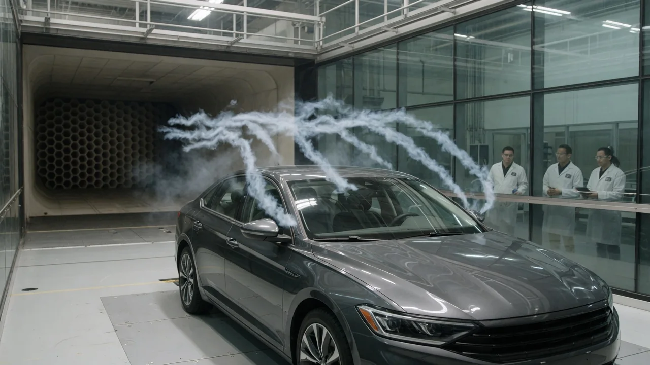
Computational fluid dynamics, usually shortened to CFD, is a way to predict how air moves around and through a car by solving the equations of fluid motion on a computer. Engineers do not need a physical model in a wind tunnel for every idea. They build a digital version of the vehicle and calculate pressure, velocity, and turbulence in the surrounding air. A car CFD simulation does not replace physical testing, but it changes how and when that testing happens.
Digital airflow model
At its core, CFD rests on the conservation laws that govern fluids: mass, momentum, and, where heat matters, energy. For moving air, these laws are written as the Navier-Stokes equations. At typical road speeds, air around a passenger car is often treated as incompressible, which simplifies the math somewhat. Even so, no one can solve these equations exactly for a shape as complex as a car. Instead, the solver breaks the problem into many small pieces and calculates approximate values of pressure and velocity in each piece. It repeats the calculation until the answers stop changing meaningfully.
Those small pieces come from a mesh. Engineers place the car inside a large virtual box that acts like a digital wind tunnel. They then fill the air volume with cells, which can number in the millions or more. The cells are made smaller where the flow changes quickly. That includes the thin boundary layer next to the body surface, the edges of mirrors and pillars, the wheels and wheel arches, the underbody, and the wake behind the car. Finer cells capture more detail, but each additional cell adds computing time and memory, so mesh design is always a balance between resolution and cost.
Turbulence is the hardest part of the model. Resolving every swirl of air directly is far too expensive for a full vehicle, so CFD codes use turbulence models. Reynolds-averaged approaches, often called RANS, predict a time-averaged flow and are relatively fast. Scale-resolving methods such as large eddy simulation and hybrid detached eddy simulation capture larger unsteady structures directly and model only the smallest ones. These methods demand much more computing power. Some development tools use lattice Boltzmann methods, which approach the flow from a different mathematical direction. Whatever the method, the outputs typically include drag and lift forces, surface pressure maps, streamlines, wake shape, and flow through cooling openings.
Inputs
The first input is geometry. Engineers usually start from the car's computer-aided design data, which must be cleaned into closed, watertight surfaces before meshing. A key decision is how much detail to include. A smooth simplified body solves quickly but ignores features that shape real airflow, such as an open underbody, exhaust components, panel gaps, brake assemblies, and wheel spoke design. Including the engine bay and cooling path adds realism and complexity. Every simplification is an assumption, and it can shift the results.
The second set of inputs describes the operating conditions, known as boundary conditions. These define the incoming air speed at the front of the virtual tunnel, the pressure at the outlet, and how the walls and ground behave. On the road, the car moves through still air while the pavement passes beneath it. For that reason, many simulations use a moving ground and rotating wheels instead of a stationary floor. Engineers may also tilt the incoming flow to represent a crosswind, known as a yaw angle. They set the vehicle's ride height and body attitude to match a particular load or speed condition.
The third group covers physical properties and solver settings. Air density, viscosity, and temperature must be specified. Components that air passes through, such as radiators and condensers, are often represented as porous zones with pressure-loss characteristics taken from component data, not modeled fin by fin. Cooling fans may be approximated in a similar way. Solver choices also count as inputs: the turbulence model, the time step for unsteady runs, and the criteria used to decide when a solution has converged. Poor choices in any of these areas can produce colorful but misleading pictures.
Validation
Engineers separate two questions. Verification asks whether the equations are being solved correctly. A common check is a mesh independence study, where the mesh is refined until key results such as drag stop changing significantly. Engineers also monitor whether forces and residual errors have settled. Validation asks a different question: does the model actually represent physical reality? A simulation can be perfectly converged and still be wrong if the geometry, boundary conditions, or turbulence model do not match the real situation.
Validation usually means comparing simulation results with physical measurements of the same configuration. In a wind tunnel, a force balance measures drag, lift, and side forces. Pressure taps on the body surface record local pressures, and flow visualization or laser-based velocity measurements show where air separates and how the wake forms. Engineers compare these data with the CFD predictions and investigate disagreements. Wind tunnels have their own departures from road conditions, including floor simulation and the influence of the tunnel walls. On-road methods such as coastdown testing therefore provide another reference point for overall resistance.
Once a simulation process has been correlated with physical data for a given type of vehicle and set of conditions, engineers can rely on it more confidently. Even then, CFD is often trusted most for relative comparisons. If two versions of a mirror or underbody panel are simulated with the same method and settings, the difference between them can be more dependable than the absolute drag value of either one. Validation is not a single event. It is repeated as methods, software, and vehicle concepts change.
Practical implications and limits
The main practical benefit of CFD is that it lets engineers explore many ideas before any hardware exists. Early in a program, designers and aerodynamicists can test variations of a roofline, rear spoiler, wheel design, or cooling inlet digitally. The aim is to narrow the field before committing to clay models or prototypes. CFD also shows the full flow field, including regions that are difficult to measure physically, such as inside wheel arches or under the floor. That insight helps explain why a change works, not just whether it does. Aerodynamics must still be balanced against styling, cooling, wind noise, stability, and cost.
The limits are real. Turbulence models can struggle to predict exactly where flow separates from curved surfaces. Unsteady phenomena such as buffeting may require expensive time-resolved runs. Results also apply only to the configuration that was modeled. A roof rack, different tires or wheels, a lowered suspension, an open window, or a heavily loaded cargo area can all change the flow around a real car. Any published aerodynamic figure reflects specific test or simulation conditions, not every way the vehicle is driven.
For car owners, the useful takeaway is to read aerodynamic claims with context. A part described as designed with CFD has been simulated, but simulation alone does not prove it helps on a particular vehicle. The value of the result depends on the inputs used and whether it was validated against physical testing. Real-world efficiency and stability also depend on speed, wind, tires, weight, and driving style. Aerodynamics is one important factor among several, not the whole story.