What Is an Induction EV Motor? Rotor Current, Field, and Control
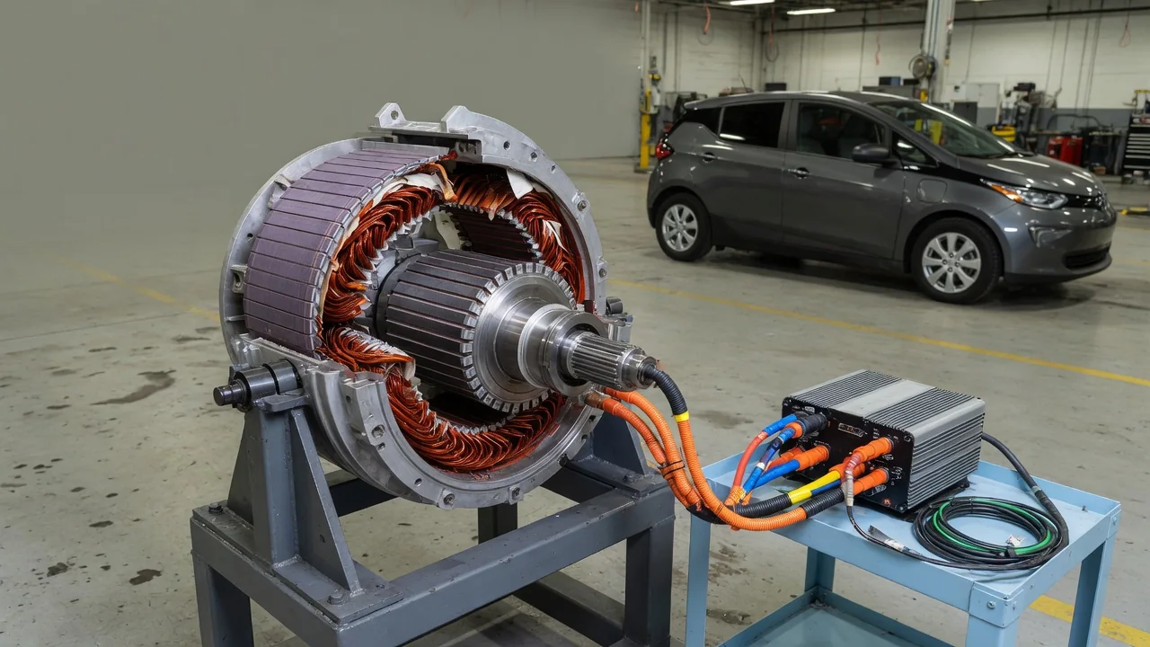
An induction EV motor is an alternating-current motor that drives the wheels without any permanent magnets in its rotor. Instead, a rotating magnetic field in the stationary part of the motor induces current in the rotor, and that induced current produces torque. To understand an induction motor in an electric car, it helps to follow three linked ideas: how current appears in the rotor, how the magnetic field is created and turned, and how the inverter controls the whole process.
Rotor Current: How the Rotor Gets Its Electricity
Most induction motors used in vehicles have a squirrel-cage rotor. It is a stack of thin steel laminations with conductive bars, usually aluminum or copper, running lengthwise through slots near the outer surface. At each end, the bars are joined by short-circuiting rings, so the conductors form closed loops. There are no external rotor windings, brushes, or slip rings, and no wires connect the rotor to the battery or inverter. All of the current flowing in the rotor arrives by electromagnetic induction.
Induction relies on a basic principle: when a magnetic field changes through a closed conductor, it generates a voltage, and that voltage drives current around the loop. In the motor, the stator's magnetic field sweeps continuously past the rotor bars. The currents induced in those bars create their own magnetic field, and the interaction between the two fields pushes the rotor in the direction the stator field is turning. The rotor is effectively dragged along behind the field.
That word behind matters. While the motor is producing driving torque, the rotor must turn slightly slower than the stator field. The difference in speed is called slip. If the rotor matched the field exactly, the bars would see no change in magnetic field, no voltage would be induced, and torque would drop to zero. This is why induction machines are also called asynchronous motors. When more torque is requested, the controller allows more slip, which increases rotor current and the force it produces, within the limits of the design.
Magnetic Field: Building a Rotating Field Without Magnets
The stator is the stationary outer part of the motor: a laminated steel core with copper windings arranged in three phases. The inverter feeds these windings three alternating currents offset in time from one another. Their combined effect is a magnetic field that rotates around the inside of the stator, even though nothing in the stator physically moves. The speed of this field, called synchronous speed, depends on the frequency of the supplied current and on the number of magnetic poles the winding is designed to create.
Because the rotor has no magnets, all of the magnetic flux has to be established by current. Part of the stator current magnetizes the iron and the narrow air gap between stator and rotor; another part works with the rotor current to produce torque. The magnetizing portion is needed whenever the motor is making torque, even lightly. Designers keep the air gap as small as practical, since a wider gap would require more magnetizing current for the same flux.
The same field also makes regenerative braking possible. If the rotor turns faster than the stator field, slip becomes negative. The induced rotor currents then oppose the rotation instead of assisting it, and the machine acts as a generator. Energy flows back through the inverter toward the battery, slowing the vehicle. No separate braking hardware inside the motor is required; the physics is the same as driving, simply with the speed relationship reversed.
Control: How the Inverter Runs an Induction Motor
The traction battery supplies direct current, but the motor needs three-phase alternating current with adjustable frequency and amplitude. The inverter provides it. Power semiconductor switches, such as IGBTs or silicon carbide MOSFETs, turn on and off many thousands of times per second using pulse-width modulation, shaping the battery voltage into approximate sine waves for each phase. Changing the frequency sets how fast the magnetic field rotates, while changing voltage and current sets the strength of the field and the torque.
Modern EV inverters commonly use field-oriented control, also called vector control. The controller measures phase currents and rotor speed, either from a sensor or by estimation, and uses a mathematical model of the motor to work out where the rotor's magnetic flux is pointing. It then divides stator current into a flux-producing component and a torque-producing component and regulates each one separately. This gives quick, smooth response to accelerator and brake inputs. Because rotor resistance changes with temperature, good control strategies account for it to keep the flux estimate accurate.
At higher speeds, the voltage the motor generates internally rises and approaches what the battery and inverter can supply. The controller responds with field weakening: it deliberately reduces the magnetizing current, which lets the motor keep spinning faster while available torque tapers off. Since an induction motor's flux comes entirely from current, it can be reduced directly. The controller also limits commanded torque to protect the battery, inverter, and motor windings from excessive current or temperature.
Practical Implications and Limits
The absence of permanent magnets has real consequences. An induction motor does not depend on rare-earth magnet materials, and when the inverter stops energizing it, there is essentially no magnetic field left in the machine. A rotor spinning freely in that state produces little drag and little voltage. This can make the design attractive in layouts where a motor sometimes turns with the wheels without contributing torque, although how a given vehicle uses its motors is a matter of that manufacturer's engineering.
The trade-offs come from the same mechanisms. Rotor current heats the rotor bars, and heat in a spinning part is harder to remove than heat in the stationary stator. During sustained heavy demand, the control system may reduce available power to protect the hardware. The magnetizing current also costs energy even at light load, so induction motors can be less efficient than comparable permanent-magnet designs at low-power cruising. Actual efficiency depends on the complete design, so motor type alone does not determine a vehicle's range or performance.
For owners, an induction drive unit is a sealed assembly with few wear items beyond bearings, seals, and its cooling system. Unusual whining, grinding, warning lights, or reduced power warrant inspection using the manufacturer's diagnostic procedures, because the motor and inverter operate at hazardous high voltage. Towing, coolant service, and other maintenance should follow the vehicle's owner's manual rather than general assumptions about motor type, since those requirements are set for each specific vehicle.