What Is an Ignition-Switched Circuit?
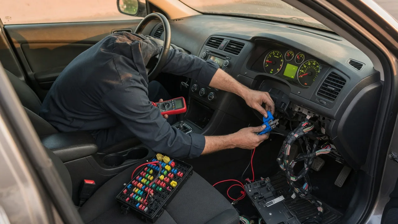
An ignition-switched circuit is any vehicle electrical circuit that gets power only when the ignition is in certain positions. It does not draw directly from the battery at all times. These circuits explain why the radio, wipers, or instrument cluster come on when you turn the key or press the start button, and go dark when you shut the car off. Knowing how ignition-switched power is controlled helps you read wiring diagrams, diagnose electrical faults, and add accessories safely.
Key state
Traditional ignition switches have several positions, commonly labeled LOCK or OFF, ACC (accessory), ON or RUN, and START. Each position closes a different set of internal contacts, and each set feeds a different group of circuits. In OFF, only constant-power circuits stay energized. These include memory functions, the clock, alarm systems, and modules that must stay ready for keyless entry. Moving to ACC typically powers comfort items like the audio system and power outlets without enabling engine-related systems. The ON or RUN position energizes the main ignition-switched loads, such as engine management, fuel pump control, the instrument cluster, and many body and chassis systems. START is a spring-loaded position that you hold only while cranking. It adds the starter control circuit.
Many circuits are not live in every position. A common arrangement shuts off accessory loads during START so that the battery's capacity goes to the starter instead of the blower motor or audio system. Some circuits stay energized in both RUN and START because the engine needs them while cranking. Vehicles with push-button start use the same idea in the form of power modes, often called off, accessory, on, and start. The difference is that the mode is selected electronically rather than by a mechanical key cylinder. The exact circuits tied to each state differ between manufacturers and models, so the owner's manual and the vehicle's wiring diagram are the authority for a specific car.
Circuit activation
The ignition state can turn a circuit on in a few general ways. In older and simpler designs, the ignition switch carries the current itself. Battery power enters the switch, and the closed contacts send it directly to the fuses and loads. This works for modest currents, but the full load passes through the switch contacts, which wear and heat up over time.
To reduce that load, many designs use the switch output only to energize the coil of a relay, often called an ignition, run, or accessory relay. The relay contacts then connect a heavier battery feed to a group of fused circuits. The switch handles a small control current, and the relay handles the working current. Newer vehicles often go a step further and treat the ignition switch or start button as just an input to a control module. This is commonly a body control module or a dedicated power distribution module. The module decides when to energize relays or solid-state outputs. It can also broadcast the ignition state over the vehicle data network so other modules wake up and go to sleep at the right time.
Because of this layering, ignition-switched does not always mean the power is cut the instant the key turns off. Some vehicles keep certain circuits alive for a delay. One example is retained accessory power, which lets the windows or audio operate until a door is opened or a timer runs out. Other vehicles wake modules briefly after shutdown for self-checks. These behaviors are design choices, not universal rules.
Wiring
A typical ignition-switched path starts at the battery positive terminal and passes through a main fuse or fusible link. From there it reaches either the ignition switch or the power input of a relay. The switched feed leaves the switch or relay and goes to a fuse panel, where individual fuses protect branch circuits running to each load. Each load completes its circuit to ground, usually through a body or engine ground point. Fuse boxes and diagrams often mark switched feeds with labels such as IGN, RUN, ACC, or RUN/START. These labels help distinguish them from battery-hot feeds, which are often labeled BATT or something similar.
Wiring diagrams may also use terminal designations. Many European manufacturers follow the DIN 72552 convention. In that system, terminal 30 is constant battery power, terminal 15 is switched ignition power, terminal 31 is ground, terminal 50 is starter control, and terminal 75 is often used for accessory power. Other manufacturers use their own circuit numbers and names. Wire colors are not standardized across the industry and can change between model years, so never rely on color alone to identify an ignition-switched wire. The dependable method is to confirm the circuit with the correct diagram and a meter.
Practical implications and limits
Owners most often look for an ignition-switched circuit when adding an accessory that should turn off with the vehicle, such as a dash camera, phone charger, or auxiliary lighting. A switched source keeps the device from slowly draining the battery while the car is parked. Start by choosing a fuse position that is live only in the key state you want. Verify it with a test light or multimeter in OFF, ACC, RUN, and START. Then use an add-a-fuse style tap so the new circuit has its own protection. Avoid circuits for airbags, engine management, brakes, and other safety or control systems, because added loads or wiring faults there can affect critical functions.
There are limits to keep in mind. An existing circuit was sized for its original loads. A high-current accessory should therefore run through its own relay, triggered by the switched feed and supplied by a separate fused feed from the battery. A circuit that tests live may still drop out during cranking. It may also stay powered for a while after shutdown because of retained power or module wake-ups, which can confuse both installations and parasitic drain testing. On vehicles with networked power management, adding loads or tapping signal wires can set fault codes or cause unexpected behavior. If the documentation for a specific vehicle is unclear, a qualified technician with factory service information is the safest resource.
Key states also help narrow down electrical faults. If a group of devices fails only in one position, the cause is often in the part of the path they share, such as a switch contact, a relay, the fuse feeding that group, or the module input that requests it. If a single device fails while others on the same feed work, look first at that device's own fuse, wiring, connector, or ground.