What Is a Wound-Rotor EV Motor? Excitation, Control and Packaging Explained
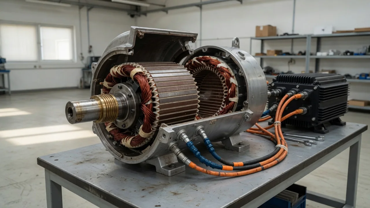
A wound-rotor EV motor is a synchronous traction motor whose rotor magnetic field comes from copper coils carrying direct current rather than from permanent magnets. Engineers usually call it an electrically excited or separately excited synchronous motor. Because the rotor field can be strengthened, weakened or switched off, this design behaves differently from the more common permanent-magnet motor. This article explains what a wound-rotor EV motor is by looking at how the rotor is energized, how the motor is controlled and how it fits inside a vehicle.
Rotor excitation
The stator of a wound-rotor electric vehicle motor is similar to that of other AC traction motors: three-phase windings, fed by the inverter, create a rotating magnetic field. The difference is in the rotor. Its laminated steel poles are wrapped in copper coils, and when direct current flows through them, the poles become electromagnets with fixed north and south polarity. These poles lock onto the rotating stator field, so the rotor turns in step with it at synchronous speed. The rotor field strength follows the field current until the steel approaches magnetic saturation, and no rare-earth magnet material is needed.
Getting current into a spinning rotor is the central engineering problem. The traditional solution uses slip rings on the shaft with stationary carbon-based brushes pressing against them, a simple and well-understood arrangement that introduces sliding contact and wear. The alternative is contactless excitation, most often a rotary transformer: an AC signal crosses a small gap between stationary and rotating coils, and a rectifier mounted on the rotor converts it back to DC for the field winding. Contactless designs remove brush wear but add parts and rotating electronics.
The term can be confusing. In industrial equipment, wound rotor often describes a slip-ring induction motor, whose three-phase rotor winding connects to external resistors. In EV discussions, it almost always means the DC-excited synchronous motor described here.
Control
A permanent-magnet motor is typically controlled through two stator current components, commonly called the d-axis and q-axis currents. A wound-rotor motor adds a third variable: the rotor field current, supplied by a separate exciter stage, often a DC-DC converter fed from the high-voltage battery. For each combination of requested torque and rotor speed, the controller chooses how to split the work among stator currents and field current. This choice is usually made with operating maps developed during design and calibration, with the goal of minimizing combined losses in the stator copper, rotor copper and iron.
The extra variable matters most at high speed. As speed rises, the voltage induced in the stator grows with both speed and rotor flux, and eventually approaches what the battery and inverter can supply. A permanent-magnet motor must counter its fixed magnet flux by injecting additional stator current, which costs energy. A wound-rotor motor can simply reduce its field current, a cleaner form of field weakening that supports a wide speed range. Adjustable excitation also lets the controller operate near unity power factor, so less inverter current is needed for a given output. Like other synchronous machines, it still requires accurate rotor position information from a resolver, encoder or sensorless estimation.
The rotor winding has high inductance, so field current changes more slowly than stator current. Controllers therefore handle fast torque changes mainly through the stator currents while the field settles. There is also a fault-handling benefit: if the inverter must shut down at speed, the controller can de-excite the rotor so the induced voltage collapses, whereas a spinning permanent-magnet rotor keeps generating voltage as long as it turns.
Packaging
Removing magnets does not automatically make the motor smaller. The rotor must hold copper coils, insulation and pole structures, and the coil ends need retention against centrifugal force at high rpm, using wedges, bands or sleeves. These requirements can limit maximum speed or call for a stiffer rotor design. As a result, achieving the same torque in the same volume as a well-optimized permanent-magnet motor is often more difficult.
Excitation hardware needs its own space. A slip-ring assembly usually sits at one end of the shaft, where it must be kept free of the oil used to cool and lubricate nearby components, and where brush dust has to be managed. A contactless exciter avoids those issues but adds axial length plus rotating diodes or other electronics that must tolerate heat and vibration. On the stationary side, the inverter housing gains an exciter circuit and the associated wiring.
Cooling is another packaging constraint. Field current produces heat inside the spinning rotor, which is harder to cool than the stator because heat must cross the air gap or travel through the shaft. Designers may use oil spray, shaft cooling or other internal paths, and the temperature limit of the rotor winding insulation can influence how much continuous output the motor can sustain.
Practical implications and limits
The efficiency profile reflects these trade-offs. Exciting the rotor always consumes some power, so losses can be relatively high when large torque is needed at low speed, such as accelerating from a stop or climbing a steep grade. At steady highway speeds, the ability to trim rotor flux can reduce iron losses and avoid the extra current that magnet-based motors spend on field weakening. How this translates into real-world range depends on the entire vehicle, including gearing, inverter design, mass and calibration, so neither motor type is universally more efficient.
Avoiding rare-earth magnets reduces exposure to magnet material supply and price swings, and it eliminates the risk of magnets losing strength after overheating. The trade-off is more copper in the rotor, an additional power stage and, in brushed designs, a sliding contact that must be engineered to last.
For owners, the design is mostly invisible during everyday driving. Brushes are wear parts in principle, but their expected service life and any inspection requirements are set by each manufacturer, so the maintenance schedule in the owner's manual is the authority. Faults in the excitation circuit typically appear as stored diagnostic codes and reduced power, and diagnosis requires model-specific service information. Towing rules, repair procedures and component replacement intervals likewise remain vehicle-specific and should not be inferred from the motor type alone.