What Is a Torsion Beam Rear Suspension? How the Twist Beam Axle Works
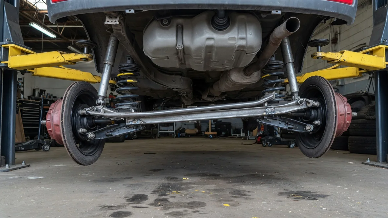
A torsion beam rear suspension, also called a twist beam or compound crank axle, is a rear suspension layout widely used on front-wheel-drive cars. It sits between a fully independent setup and a solid axle. Two trailing arms carry the rear wheels, and a cross member joins them. That member is designed to twist. Understanding torsion beam axle operation comes down to three ideas: how the arms are connected, how the beam twists, and why the whole assembly packages so efficiently.
Connected trailing arms
The foundation of the design is a pair of trailing arms. Each arm pivots on a bushing mounted to the body ahead of the wheel, and the wheel hub or stub axle is attached at the rear end of the arm. As the wheel moves over bumps, the arm swings up and down around its front pivot, tracing an arc. On its own, this is the classic trailing arm motion: the wheel moves mainly vertically, with little sideways travel and relatively small change in track width.
What makes a torsion beam different is the cross member welded or otherwise rigidly joined between the two arms. The arms and beam usually form a single U-shaped or H-shaped assembly. Where the beam is placed along the arms matters. If it sat directly in line with the pivot bushings, the layout would behave much like two independent trailing arms linked by an anti-roll bar. If it sat directly between the wheel centers, it would act more like a rigid axle. Most torsion beam designs place the cross member somewhere between those extremes, which is why the term compound crank is used. The chosen position is a tuning decision that shapes how the suspension behaves, and it varies from one design to another.
Twist
The beam is engineered to resist bending while allowing torsion. A common way to achieve this is an open cross section, such as a U, V, or C shape, which is stiff when loaded in bending but comparatively easy to twist along its length. Some designs add a separate torsion bar or a tube inside or alongside the beam to raise its torsional stiffness without redesigning the whole assembly. The material, wall thickness, and section shape together determine how much the beam resists twisting.
When both rear wheels rise or fall together, as they do when the car is loaded evenly or passes over a bump that spans the full width of the road, both arms rotate by the same amount. The beam simply swings with them and does not twist. When the body rolls in a corner, or when only one wheel hits a bump, the arms rotate by different amounts. The beam is then forced to twist, and its torsional resistance acts like a built-in anti-roll bar, transferring some load from one side to the other and adding roll stiffness at the rear axle.
Twist also affects wheel alignment during movement. Because the beam is offset from the pivots, a twisting beam causes the wheels to change camber as the body rolls, and the result falls somewhere between trailing arm and solid axle behavior. Toe can change as well, partly through geometry and partly through the compliance of the pivot bushings under cornering and braking forces. Engineers often shape and orient these bushings deliberately to control how the rear wheels steer under side loads, since the beam itself offers no adjustable links for that purpose.
Packaging
Packaging is one of the main reasons the layout is so common. A torsion beam assembly has few parts: two arms, a cross member, two body mounting points with bushings, plus springs and dampers. There are no separate upper and lower control arms, no toe links, and no subframe is necessarily required. The assembly can often be built and installed as a single module, which simplifies manufacturing and reduces part count.
The compact shape also frees space. Because the beam usually runs low and across the car behind or below the rear seat area, and the springs and dampers can be mounted in separate positions on the arms, designers can keep intrusion into the cargo floor and passenger area modest. That leaves room for a lower trunk floor, a fuel tank, a spare wheel well, or exhaust routing. The trade-off is that the arms and beam occupy the space where driveshafts and a rear differential would need to go, so the layout is generally suited to cars with non-driven rear wheels. Rear-drive and many all-wheel-drive vehicles typically use other suspension types for that reason.
Practical implications and limits
For an owner, the most noticeable consequence is that the rear wheels are not fully independent. A pothole or sharp edge under one wheel partly influences the other side through the beam. On smooth roads this is often hard to detect, while on broken surfaces a torsion beam car may feel busier at the rear than one with a multi-link setup. How much this is felt depends heavily on the specific tuning of springs, dampers, bushings, and beam stiffness, so the suspension type alone does not predict ride quality or handling for any particular vehicle.
Maintenance is usually straightforward. The main wear items tend to be the pivot bushings, the dampers, and the springs. Worn pivot bushings can show up as clunks over bumps, a vague or shifting feel from the rear during lane changes, or uneven rear tire wear. Because rear camber and toe are set by the shape of the beam and the bushing positions, they are typically not adjustable through conventional alignment hardware. If a rear alignment check shows values out of the specification for the vehicle after a curb strike or collision, the cause may be a bent arm or beam rather than something that can be dialed out.
It is also worth keeping expectations realistic in both directions. A torsion beam is not inherently crude: careful engineering can deliver stable, predictable behavior suited to everyday driving. Equally, it has fewer tuning freedoms than a multi-link design, so its abilities depend on how well it was matched to the car. When diagnosing a specific vehicle, the service information for that model remains the authority on inspection procedures, specifications, and torque values.