What Is a Rotor in an EV Motor? Rotation, Magnets, Induction and Bearings
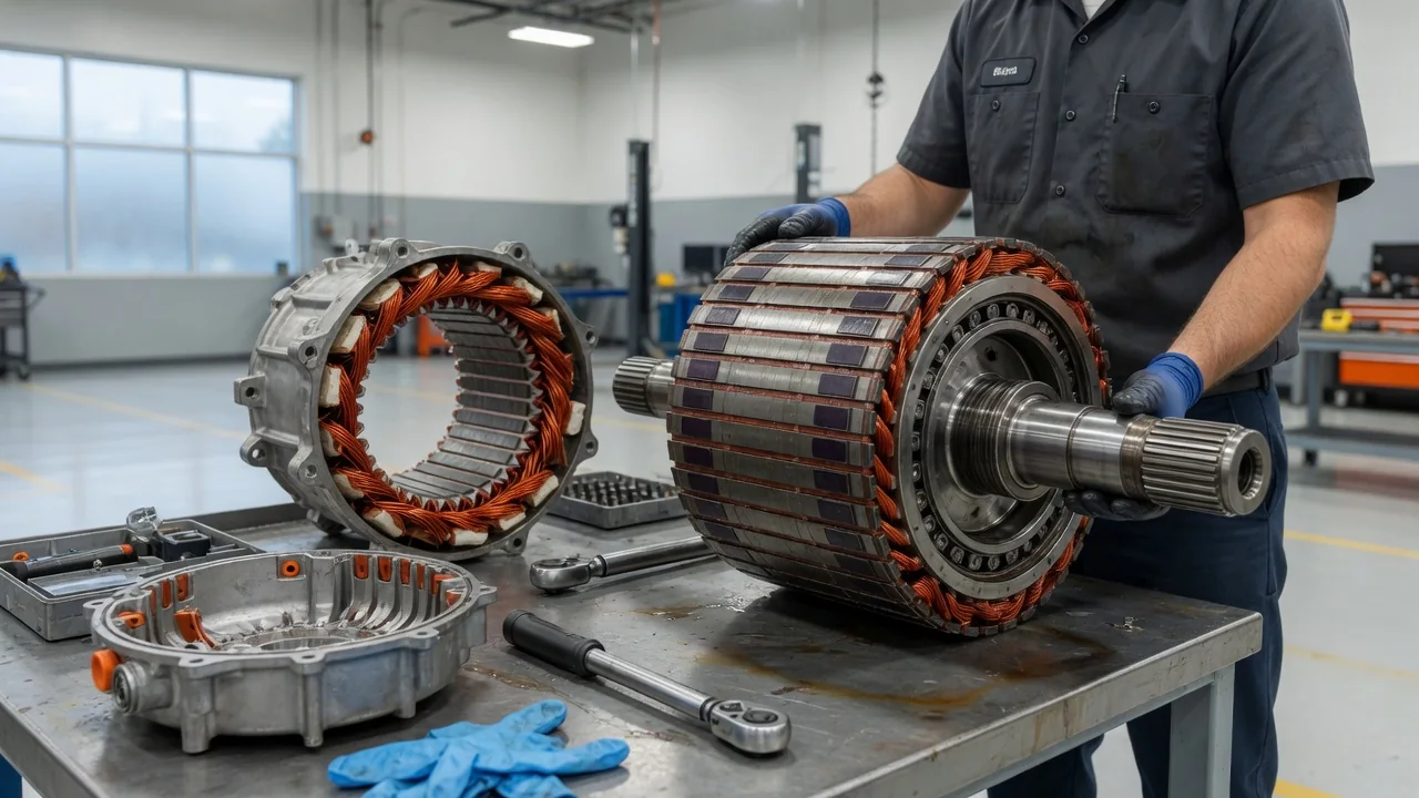
In an electric vehicle motor, the rotor is the part that spins. It sits inside the stationary stator, separated from it by a narrow air gap, and turns a shaft that delivers torque through the reduction gearing to the wheels. Knowing what an electric vehicle motor rotor does, how its magnetic field is created, and what keeps it turning true helps explain how EV drive units deliver smooth power and why they are built the way they are.
Rotation: How the Rotor Turns Electricity into Motion
The rotor does not receive power on its own; the work starts in the stator. The inverter converts direct current from the high-voltage battery into three-phase alternating current and feeds it to the stator windings. By timing the current in each phase, the inverter creates a magnetic field that sweeps around the inside of the stator. The rotor has its own magnetic field, and the attraction and repulsion between the two fields produce torque. As the stator field rotates, the rotor is pulled along with it. Most EV traction motors work this way without a mechanical commutator, so there is no brush assembly wearing against a spinning surface.
Physically, the rotor is usually a cylinder built from many thin steel laminations stacked together and pressed onto a shaft. The laminations are insulated from one another to limit eddy currents, which would otherwise waste energy as heat. Because EV motors commonly spin much faster than a gasoline engine revs, the rotor must be carefully balanced and strong enough to resist the outward forces at high speed. A reduction gear between the motor and the wheels trades that high rotor speed for greater torque at the axle.
Precise control depends on knowing what the rotor is doing. Many designs use a position sensor, often a resolver mounted on the shaft, so the inverter can time the stator currents to the rotor's exact angle and speed; some control strategies estimate position from electrical signals instead. The relationship also works in reverse. During regenerative braking, the wheels drive the rotor, the motor acts as a generator, and the inverter routes the recovered energy back to the battery.
Magnet or Induction: Where the Rotor's Magnetic Field Comes From
A permanent magnet rotor carries magnets that provide its field at all times. They may be fixed to the surface of the rotor or, very commonly in automotive motors, inserted into slots within the laminations, a layout known as an interior permanent magnet design. These magnets are often rare-earth types such as neodymium-iron-boron. The rotor turns in step with the stator field, which makes this a synchronous motor. Because the rotor needs no current to create its field, this design tends to be efficient over a wide operating range. The tradeoff is that the magnets are always active: a spinning rotor induces a back voltage in the stator, so at high speed the inverter must use field weakening, and the motor can create some drag losses when the car coasts.
An induction rotor has no magnets. Its most common form is the squirrel cage: copper or aluminum bars set into the laminations and joined at each end by shorting rings. The rotating stator field induces current in those bars, and that current creates the rotor's own field. For induction to occur, the rotor must turn slightly slower than the stator field, a difference called slip, so this is an asynchronous motor. The design is robust, avoids rare-earth materials, and produces very little magnetic drag when it is not energized. On the other hand, current flowing in the rotor bars generates heat inside the rotor, where it is harder to remove, and efficiency at light loads is generally lower than in a comparable permanent magnet design.
A third approach is the wound-rotor, or externally excited, synchronous motor. Here the rotor carries copper windings that receive current through slip rings and brushes or a contactless transfer system, letting the controller adjust the rotor field without permanent magnets. Which rotor type a specific vehicle uses is a design decision, and the manufacturer's technical documentation is the reliable source for that detail.
Bearings: What Keeps the Rotor Centered
The rotor shaft is supported by bearings, typically rolling-element ball bearings at each end of the motor. Their first job is to keep the rotor precisely centered. The air gap between rotor and stator is small, and it must stay uniform: an off-center rotor creates uneven magnetic pull, noise and vibration, and in a severe case the rotor could contact the stator. The bearings also carry radial loads and any axial thrust from the gearing, all at high rotational speed. Depending on the design, they are sealed and grease-packed or lubricated by the oil that circulates through an integrated drive unit.
EV motor bearings face a hazard that ordinary wheel bearings do not. Fast switching in the inverter can create a common-mode voltage that couples onto the rotor shaft. If that voltage discharges through a bearing, tiny electrical arcs can pit the races and rolling elements, and over time this can produce a frosted or fluted wear pattern. Designers counter this with measures such as shaft grounding rings or brushes, insulated bearings, bearings with ceramic rolling elements, or insulating coatings.
When motor bearings wear, the usual signs are a whine, growl or rumble that changes with vehicle speed, sometimes accompanied by vibration. Those symptoms are not unique to the motor, though. Reduction gears, wheel bearings, tires and loose components can make similar sounds, so a proper diagnosis is needed before blaming the rotor bearings.
Practical Implications and Limits for Owners
For most owners, the rotor is not a maintenance item. Permanent magnet and squirrel cage rotors have no brushes to replace and no adjustments to make, and the rotor sits sealed inside the drive unit. The maintenance that indirectly protects it, such as drive unit fluid and coolant service, is set by each manufacturer's schedule, so the owner's manual is the place to check.
Temperature is the main practical limit on what the rotor can deliver. Magnet strength falls as temperature rises, and severe overheating can permanently weaken permanent magnets, while induction rotors must shed heat produced inside the rotor itself. To protect these parts, the vehicle's control system monitors temperatures and can reduce available power during sustained heavy demand, such as repeated hard acceleration or long climbs under load. Reduced output in those conditions is usually protective behavior rather than a fault, although the exact thresholds and responses differ by vehicle.
Repair is also limited by design. The rotor lives inside a high-voltage assembly, so work requires proper training, de-energizing procedures and protective equipment. Removing a permanent magnet rotor needs special fixtures because its magnets pull strongly toward the stator steel. Some service procedures allow bearing or seal replacement, while others call for replacing the complete motor or drive unit. The vehicle-specific service manual defines what is serviceable, and it is the right reference before any disassembly is considered.