What Is a Pressure Tap on a Test Car? Location, Data and Design
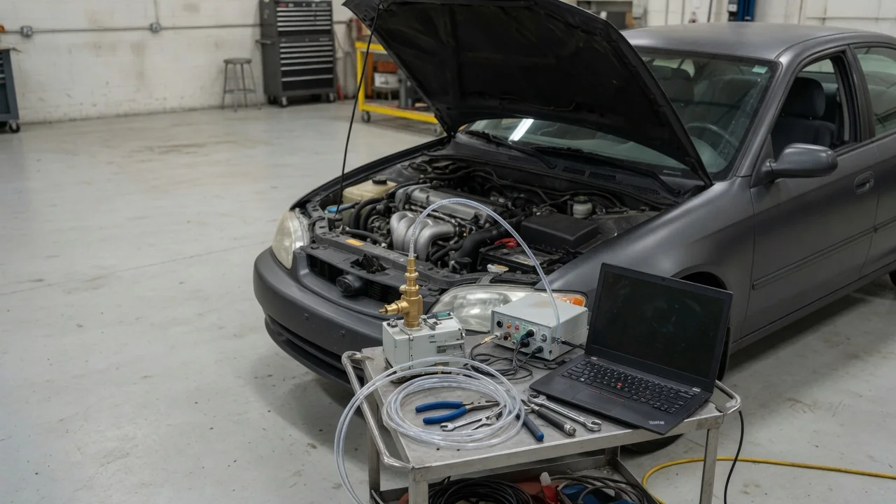
A pressure tap is a small, carefully drilled hole in the surface of a test car that connects through tubing to a pressure sensor. Instead of measuring the overall force of the air on the vehicle, it records the local static pressure at one precise point. Engineers place many of these taps across a body to build a detailed map of how air loads the car, which helps explain drag, lift and cooling behavior.
Sensor location: where taps are placed on a test car
Each tap is placed to answer a specific question about the airflow. A common starting point is the front of the car, where air slows down and pressure rises near the stagnation region on the bumper and grille. From there, engineers often run rows of taps along the centerline over the hood, windshield, roof and rear window, because the pressure distribution along that line shows where the flow accelerates, where it slows, and whether it stays attached as it turns down toward the tail. Areas with sharp changes in curvature, such as the hood leading edge, the base of the windshield and the A-pillars, tend to receive closer spacing because pressure can change rapidly over a short distance there.
The rear of the vehicle is just as important. Taps on the rear face, tailgate or trunk lid measure the low pressure in the wake, which is closely linked to pressure drag. Other locations depend on the development program. Taps under the car can show how the underbody, diffuser or floor panels behave. Taps in and around wheel arches reveal the influence of rotating wheels and tire wakes. Taps ahead of and behind the radiator or other heat exchangers help engineers estimate how much pressure difference is available to drive cooling air. Smaller components such as mirrors, spoilers and side sills may also be instrumented while they are being developed.
Data collection: from a small hole to a pressure map
A pressure tap itself is passive. It is simply an opening, usually with a short fitting behind the surface, joined to flexible tubing that carries the pressure to a transducer. Because a test vehicle may carry a large number of taps, the tubes are commonly routed to electronic pressure scanners, which contain many sensors in one compact module and can read numerous channels in rapid sequence. Each measurement is taken relative to a reference pressure, such as the freestream static pressure in a wind tunnel or a carefully chosen reference port during road testing.
The raw readings are then usually converted into a dimensionless pressure coefficient, which relates the local pressure to the reference pressure and the dynamic pressure of the oncoming air. This makes results comparable between runs at different speeds and conditions. Engineers typically record a time-averaged value for each tap to describe the steady pressure field, and when the instrumentation supports it, they also examine fluctuating pressure to study unsteady effects such as vortex shedding or buffeting. The values can be plotted along a line, drawn as contour maps across the body, and compared with computational fluid dynamics predictions or with force measurements from a wind tunnel balance to check that the overall picture is consistent.
Design decisions behind vehicle aerodynamic pressure taps
The quality of tap data depends heavily on small construction details. The hole should be drilled perpendicular to the local surface, sit flush with it and have a clean edge without burrs, raised lips or rounded corners, because any of these can locally disturb the flow and bias the reading. Tap holes are kept small relative to the features being studied so that the measurement represents a point rather than an average over a large area, but not so small that they clog easily or respond too slowly. Painted or taped surfaces need particular care so that coatings or adhesive do not partly block the opening.
Tubing design involves its own trade-offs. Long or narrow tubes damp and delay pressure fluctuations, which is acceptable for time-averaged measurements but can distort unsteady data unless the tubing response is characterized and corrected. Placing scanners close to the taps shortens the tubing, yet the scanners and cables must fit inside the body without disturbing the external flow or interfering with cooling and mechanical systems. Leaks, kinks and tubes connected to the wrong channels are well-known sources of error, so labeling and leak checks are a standard part of installation.
Teams also decide how many taps to install and where to concentrate them. More taps give a finer pressure map but add cost, installation time and data handling. A common approach is to use dense rows where steep pressure gradients are expected and sparser coverage on flatter panels, while keeping some matching pairs on both sides of the car to check for flow asymmetry or the effects of yaw.
Practical implications and limits
Pressure taps measure only the pressure acting normal to the surface at discrete points. They do not capture skin friction drag, and integrating a limited number of taps into an overall force is an approximation that depends on how well the taps cover the regions that matter. For that reason, taps are usually used to explain why a car behaves as it does, while total drag and lift are taken from balance measurements or other force-based methods. In separated, highly turbulent regions, the average reading at a single tap can also hide large swings in pressure over time.
Results are also tied to the test conditions. A car on the road experiences gusts, crosswinds, traffic and changing ride height, while a wind tunnel offers controlled flow but may represent ground and wheel motion differently depending on its equipment. Pressure data from one configuration does not automatically transfer to another body style, trim level or accessory setup, so conclusions are vehicle-specific unless they describe a general mechanism.
For interested owners, the most useful takeaway is recognition. Small holes, strips of tape or bundles of tubing on a camouflaged prototype may indicate aerodynamic instrumentation such as pressure taps, but their presence alone does not reveal how efficient or stable the final production car will be. They show that engineers are studying the airflow at those spots, not what the outcome of that study was.