What Is a Mass Airflow Sensor?
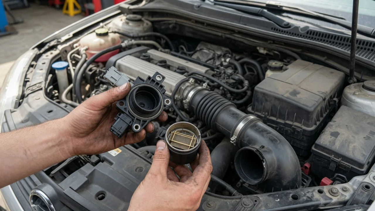
Anyone asking what is a mass airflow sensor is really asking how an engine knows how much air it is breathing. This small electronic device sits in the intake tract and reports incoming air to the engine computer, which uses that reading to decide how much fuel to deliver. Understanding its role makes drivability symptoms and diagnostic results much easier to interpret.
Sensor location concept
A mass airflow sensor, often shortened to MAF, is placed where all the air entering the engine must pass it. On most gasoline vehicles that means the intake duct between the air filter housing and the throttle body. Positioning it after the filter keeps the sensing element in clean air, and placing it ahead of the throttle means it measures the full stream before that air is divided among the cylinders. Anything that enters downstream of this point goes uncounted, which is why placement matters so much.
Under the hood, the sensor usually appears as a plastic housing or a small insert in the intake tube with an electrical connector attached. Some designs are built into the air filter box lid, while others sit in a separate section of ducting. Turbocharged engines, diesel engines and vehicles that rely on a manifold pressure sensor instead may be arranged differently, and some engines use both types of sensor together. The owner's manual or service information for the specific vehicle confirms what is fitted and where.
Engine calculation
Most modern units use a heated element, either a fine wire or a thin film, exposed to the passing air. Airflow cools the element, and the sensor's circuitry supplies more current to hold it at a set temperature. The harder the engine breathes, the more current is needed, and that change becomes an electrical signal. Because denser air carries away more heat, the reading reflects the mass of air rather than just its volume, which is what matters for combustion.
The engine computer combines this signal with engine speed, intake air temperature, throttle position and other inputs to calculate engine load and the fuel injector opening time. The goal is a fuel quantity that matches the measured air so the mixture burns cleanly. Oxygen sensors in the exhaust then check the result, and the computer applies fuel trim corrections if the mixture comes out rich or lean. Airflow data can also influence ignition timing and, on many vehicles, automatic transmission shift behavior, though strategies differ by manufacturer.
Fault clues
When the airflow reading is wrong, the fuel calculation is wrong with it. A sensor that underreports air can leave the engine running lean, producing hesitation, surging or stumbling under acceleration. One that overreports can cause a rich mixture, with a fuel smell, dark exhaust smoke or poorer fuel economy. Rough or unstable idle, hard starting, stalling shortly after startup and an illuminated check engine light are other commonly reported clues, though none of them points only to this component.
Stored fault codes relating to the airflow circuit or to lean and rich conditions are evidence to interpret, not proof that the sensor itself has failed. A split intake hose, a loose clamp, a vacuum leak, a clogged air filter, damaged wiring or a corroded connector can produce very similar results. Contamination on the sensing element, sometimes from dust or oil residue, can also skew readings without any electrical failure. Code definitions and setting conditions vary between manufacturers, so they need confirming against information for the particular vehicle.
Everyday Use and Observations
In normal driving the sensor works unnoticed, responding continuously as the throttle opens and closes. At idle the engine draws relatively little air and the signal is low; during hard acceleration or highway climbing the flow rises sharply and the signal follows. A healthy system translates those changes into smooth, predictable throttle response. Drivers tend to notice the sensor only indirectly, through how evenly the engine idles, how cleanly it pulls away from a stop and how consistent fuel consumption stays over time.
A scan tool that displays live data lets an owner or technician watch the airflow reading directly, usually in grams per second. The useful observation is the pattern rather than any single number: the value should rise and fall smoothly with engine speed and load, without dropouts or sudden jumps. What counts as a normal figure depends on engine size, design and operating conditions, so readings are best compared with specifications for that engine rather than with general rules of thumb.
Limits and Next Steps
The sensor has clear limits. It can only report air that actually flows past it, so leaks between the sensor and the engine upset the mixture even when the unit is working perfectly. It also cannot identify why airflow is low or high, only that it is. For that reason a sound diagnosis looks at the whole intake path, the air filter condition, the wiring and connector, and fuel trim behavior before any conclusion is drawn about the sensor itself.
Sensible next steps begin with simple visual checks: a properly seated air filter, intact ducting and a secure electrical connector. The sensing element is delicate and should not be touched or cleaned with anything other than a product intended for it, following the vehicle maker's guidance. If symptoms or warning lights persist, a qualified technician can test the signal against vehicle-specific data and rule out related faults. Replacing parts on the strength of a code alone risks spending money without fixing the underlying cause.