What Is a Charging Connector Proximity Signal? Plug Presence, Interlock and Release
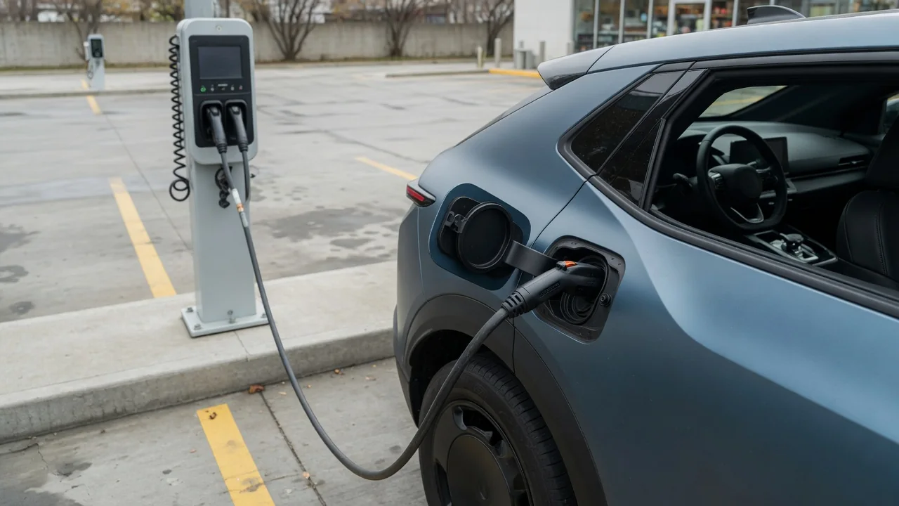
A charging connector proximity signal is a simple electrical circuit, separate from the power pins, that tells an electric vehicle whether a charging plug is inserted in its inlet. In common AC charging standards it is usually called proximity pilot or proximity detection. Despite the name, it does not measure distance and does not carry charging data. It reports connection state, and on some connectors it also reports cable capability or latch position. This article explains how EV connector proximity detection supports plug presence, safety interlocks and safe release.
Plug presence
Inside the connector, the proximity circuit is typically a resistor network placed between a dedicated proximity pin and the protective earth pin. When no plug is inserted, the vehicle's sensing input on that pin sees an open circuit, so its monitoring electronics read a level that means nothing is connected. Once the plug is seated, the resistor completes the path to earth, the level at the vehicle's sensing point changes to a value the standard associates with a connected plug, and the onboard charging controller recognizes that a connector is present. Because this is a passive resistance measurement, it works even before the charging station has applied any power to the cable.
The amount of information carried by the proximity circuit depends on the connector standard. On the J1772 connector used in North America, it mainly confirms that a plug is present and whether its latch is engaged. On the IEC Type 2 connector used widely in Europe and other regions, the resistor value also encodes the current rating of the cable assembly. On sockets that accept a detachable cable, the charging station can read that resistor on its own side as well. DC fast-charging connectors built on these designs, such as the Combined Charging System, keep a proximity contact too, with values and logic defined by the relevant standard rather than by individual vehicles.
The proximity signal works alongside, but separately from, the control pilot. The control pilot is an active signal generated by the charging equipment to indicate availability and permitted current and to coordinate when power is switched on. Proximity answers a narrower question: is a connector physically mated, and in what mechanical state is it?
Safety interlock
The most familiar use of the plug-presence signal is as an input to safety interlocks. In a typical arrangement, the vehicle will not request or accept charging power until the proximity circuit shows a properly connected plug, and the charging station will not close its own contactors until the control pilot handshake indicates the vehicle is ready. Together, these conditions mean the high-power contacts in the connector are normally energized only after the plug is fully mated, not while it is being inserted or lying loose.
Many electric vehicles also use the proximity signal as a drive-away interlock. While a charging connector is detected in the inlet, the vehicle's control software prevents it from being shifted into gear or driven, which reduces the risk of pulling away while still tethered to a charging station. How this is implemented, what message the driver sees and whether any override exists are decisions made by each manufacturer, so the owner's manual is the authority for a particular vehicle.
Where the proximity resistor encodes cable capacity, it forms an additional interlock on current. If the detected value indicates a lower-rated cable, the charging system is expected to limit current accordingly, and an invalid or unrecognized value should result in no charging rather than unrestricted charging. This protects the cable and connector from overheating; it is a protective feature, not a performance setting.
Release
On a J1772 connector, the proximity circuit is linked to the release latch. Pressing the latch button operates a small switch inside the handle that changes the resistance the vehicle sees, even though the plug is still physically in the inlet. The vehicle interprets this change as an imminent disconnection and is expected to stop drawing current promptly, so that by the time the pins separate, little or no current is flowing. This reduces arcing at the contacts, which would otherwise wear the pins and could create a hazard.
Connectors without a thumb latch, such as Type 2, handle release differently. The vehicle inlet, and often the station socket, uses an electrically driven locking pin that holds the plug in place during charging. The vehicle normally ends the charging session and opens its power path before commanding the lock to release, commonly when the driver unlocks the car or stops the session through the vehicle's controls. The proximity signal then confirms when the plug has actually been removed, allowing the vehicle to clear its charging and drive-away states.
In both designs the principle is the same: the electrical shutdown should finish before mechanical separation begins. The proximity signal is how the vehicle knows which phase it is in, whether the plug is fully seated, release has been requested, or the plug is gone, and the charging controller uses that state to sequence its actions.
Practical implications and limits
Because so much depends on a small passive circuit, faults in it tend to appear as everyday annoyances: charging that never starts, a car that reports no plug when one is clearly inserted, a car that will not drive after being unplugged, or sessions that stop when the handle is bumped. Possible causes include a worn or sticky latch switch, a damaged handle, dirt or moisture in the pins, or a fault in the vehicle's inlet wiring. None of these symptoms is unique to the proximity circuit; control pilot problems, station faults and vehicle software can produce similar behavior, so diagnosis calls for proper test equipment and the manufacturer's procedures.
Adapters and replacement cables must reproduce the signaling that the vehicle and station expect for the connector types involved. An adapter that presents the wrong state, or a cable whose resistor misrepresents its rating, can defeat the interlocks that keep charging safe. Bypassing or modifying the circuit to force a session to start removes protections that exist for good reason and is not a reasonable workaround.
It also helps to be clear about what the signal cannot do. It does not sense a plug approaching before contact, it does not negotiate charging power, and on its own it does not prove that energy is flowing. Exact resistance values, timing and responses are set by the applicable standards and by each manufacturer's implementation, so a general explanation describes the mechanism rather than the precise behavior of any specific vehicle.