What Is a Brake Hydraulic Modulator?
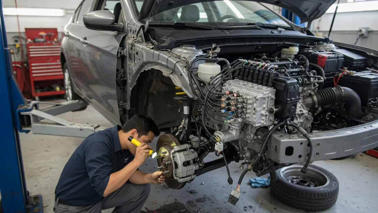
A brake hydraulic modulator is the valve-and-pump assembly that lets an anti-lock braking system change brake pressure at individual wheels without waiting for the driver's foot. Often called the ABS hydraulic control unit, it sits between the master cylinder and the wheel brakes and is commonly paired with, or bolted directly to, the electronic control module. When a wheel begins to lock, or when stability control needs to brake one corner, the modulator holds, releases or rebuilds pressure in rapid cycles.
Valves and pump
The modulator is built around a metal housing, typically aluminum, with internal drilled passages connecting the brake lines. Solenoid valves are pressed into this block, and in a common layout each controlled wheel channel has two of them: an inlet valve and an outlet valve. The inlet valve is normally open, so when no current flows it passes fluid from the master cylinder straight to the brake. The outlet valve is normally closed, sealing the wheel circuit from the return side. The control module energizes the coils to change these states. With the coils off, the unit therefore passes ordinary braking through unchanged.
The second key element is the return pump, usually a small piston pump driven through an eccentric by an electric motor mounted on the housing. Next to it, most designs include a low-pressure accumulator, a small chamber that briefly stores fluid released from a wheel brake. The pump draws fluid out of that accumulator and pushes it back toward the master cylinder side of the circuit, so the system does not run short of fluid during a long anti-lock stop. Some units add damping chambers to smooth pump pulses.
Systems that add electronic stability control and traction control need extra hardware in the same block. Typical additions are switching or isolation valves that can separate the master cylinder from the wheel circuits, and suction or high-pressure valves that let the pump draw fluid from the master cylinder and reservoir side. Many such units also carry a pressure sensor so the controller can estimate how hard the driver is pressing. Exact valve counts and channel layouts vary; some older or simpler systems control both rear wheels together through a shared channel.
Pressure paths
During ordinary braking the modulator is mostly passive. Fluid leaves the master cylinder, passes through any open switching valve, flows through the open inlet valve for each wheel and reaches the caliper or wheel cylinder. The outlet valves stay closed, the pump stays off, and pressure at the wheel follows pedal effort. Brake circuits are usually split into two independent halves, either front and rear or diagonally, and the modulator keeps those halves separated internally so a leak in one circuit does not drain the other.
When wheel speed signals show one wheel slowing much faster than the vehicle, the controller runs a pressure cycle on that channel. First it closes the inlet valve to hold the existing pressure. If the wheel still decelerates too sharply, it opens the outlet valve, letting fluid escape into the accumulator so pressure drops and the tire regains grip. Once the wheel speeds up again, the outlet closes and the inlet reopens to rebuild pressure in steps. Meanwhile the pump returns the stored fluid toward the master cylinder, which is why the pedal pulses and the unit buzzes during an anti-lock stop.
Stability and traction control need pressure the driver did not request. To create it, the controller closes the switching valve to isolate the master cylinder, opens the suction valve, and runs the pump so it draws fluid in and pressurizes the selected circuit. Inlet valves for wheels that should not brake are closed, and the inlet and outlet valves on the target wheel then trim pressure using the same hold, release and increase logic used in anti-lock operation.
Faults
Many modulator problems are electrical and are detected by the control module itself. Common categories include an open or shorted valve solenoid, a pump motor that fails to run or does not respond as expected, a faulty power supply or relay circuit, and internal faults in a control module attached to the hydraulic unit. The system typically performs self-checks at startup and during driving, stores diagnostic trouble codes, and illuminates the ABS or stability control warning lamp. Wheel speed sensor faults trigger the same lamps, so a warning light alone does not identify the modulator as the cause.
Hydraulic faults are harder to pin down. Old fluid that has absorbed moisture, or debris from worn components, can leave a valve sticking or not sealing fully. An outlet valve that leaks may let pressure bleed away and lengthen pedal travel, while an inlet valve that does not open properly can reduce braking at one wheel and cause a pull. Air trapped in the internal passages, for example after the system ran low on fluid, can produce a soft pedal that ordinary bleeding does not cure. For this reason some manufacturers specify a scan-tool procedure that cycles the valves and pump while bleeding.
Other symptoms include a pump that runs at unexpected times, unusual noise from the unit, or anti-lock activation at low speed on dry pavement, which can also stem from sensor or tone-ring problems. Corroded connectors and damaged wiring near the unit can mimic internal failure. Because these symptoms overlap with faults elsewhere, accurate diagnosis normally relies on stored codes, live data and component tests described in the vehicle's service information.
Practical implications and limits
For the driver, a pulsing pedal and grinding or buzzing sound during a hard stop are signs the modulator is working, not failing. If a fault disables anti-lock and stability functions, the normally open inlet valves usually leave conventional braking available, but wheels may lock under heavy braking and the stability aids will be absent. A red brake warning lamp generally signals a more serious base-brake or fluid issue than an amber ABS lamp alone; the owner's manual defines what each lamp means for that vehicle.
Maintenance has a direct effect on modulator life. The small valve passages are sensitive to contaminated or degraded fluid, so following the manufacturer's fluid type and replacement interval matters. Service work also differs by vehicle: some units can be bled conventionally, others need the scan-tool routine, replacement units may arrive pre-filled or dry, and some require coding or configuration after installation. A generic procedure copied from another model can leave air in the unit or a fault code unresolved.
The valve-and-pump layout described here is a general mechanism, not a description of every car. Newer integrated brake systems and brake-by-wire designs can combine pressure generation and modulation in a single unit, and hybrid or electric vehicles may blend hydraulic braking with regenerative braking. Whatever the hardware, a modulator cannot add grip beyond what the tires and road surface provide; it helps maintain steering control, and on loose gravel or deep snow stopping distances can still be longer than with locked wheels.