What Is a Battery Thermal Management Valve? Routing, Modes and Faults
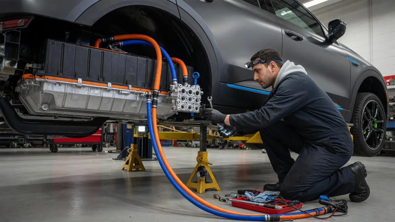
A battery thermal management valve is an electrically controlled coolant valve that decides where coolant flows in an electric or plug-in hybrid vehicle's thermal system. It does not set temperature directly. Instead, it connects or separates loops so the battery pack can be cooled, warmed, or left alone as conditions require. Understanding the EV thermal valve function helps explain why one small component can affect charging speed, driving range, and cold-weather behavior, and why its faults often show up in unexpected ways.
Coolant routing
Most liquid-cooled battery packs sit in a coolant circuit that runs through cold plates or channels in contact with the cells or modules. That circuit rarely works alone. Depending on the design, it can be linked to a front radiator, a chiller that transfers heat into the air-conditioning refrigerant, an electric coolant heater, a heat pump system, and the loop that cools the drive motor and power electronics. The thermal management valve sits at the junction of these paths. By moving an internal element, it opens some ports and closes or restricts others, which determines which heat sources and heat sinks the battery coolant actually passes through.
Valve designs vary. Some systems use several simple two-way or three-way valves, each switching one branch. Others use a single multi-port rotary valve, sometimes described as an integrated coolant valve or coolant hub, that can produce many flow combinations from one actuator. In common configurations, a small electric motor turns the valve element through a gear set, and a position sensor reports the actual position back to a thermal management control module. Because the valve only redirects flow, it works together with one or more electric coolant pumps that provide the circulation itself.
The control module chooses valve position using inputs such as cell temperatures, coolant temperatures at several points, ambient temperature, cabin heating and cooling requests, and charging status. The exact routing logic, number of ports, and available paths are specific to each vehicle platform, so a coolant diagram for one model should not be assumed to apply to another.
Operating modes
Although the names and number of modes differ between manufacturers, the general functions fall into a few groups. In passive or ambient cooling, the valve routes battery coolant through the front radiator so outside air removes heat. This uses little energy and suits conditions where the outside air is meaningfully cooler than the battery. When that is not enough, for example in hot weather, under sustained high load, or during DC fast charging, the valve sends coolant through the chiller so the air-conditioning system can bring the temperature lower than ambient air could.
Heating modes do the opposite. In cold conditions the valve can direct coolant through an electric heater or a heat pump heat exchanger, or connect the battery loop to the drive unit loop so waste heat from the motor and inverter warms the pack. Some systems can also deliberately operate components less efficiently to generate extra heat, with the valve routing that heat to the battery. Preconditioning before fast charging, whether triggered by navigating to a charger or by a manual request, typically relies on these heating or cooling paths.
There is also usually an isolated or bypass mode, in which the battery loop circulates on its own without adding or removing much heat. This helps even out temperature differences across the pack and avoids spending energy when the battery is already in its preferred range. Systems that can link loops in series or keep them in parallel switch between those arrangements using the same valve hardware.
Faults
Because the valve combines a mechanical element, an electric actuator, and a sensor, faults can come from several sources. The valve element may stick or bind, sometimes because of debris, deposits, or degraded seals, so it cannot reach the commanded position. The actuator motor or its internal gears can fail. The position sensor can report incorrect values, leaving the controller unsure where the valve actually is. Wiring and connector problems, including corrosion or damaged terminals, can interrupt power or communication. Internal leakage across seals may let coolant pass into a branch that should be closed, which weakens a mode without causing a complete failure.
When the control module detects a mismatch between commanded and actual position, an out-of-range sensor signal, or a circuit fault, it typically stores a diagnostic trouble code and may display a warning. Depending on the vehicle and the position where the valve is stuck, symptoms can include slower DC fast charging, reduced power output, longer warm-up times, weaker cabin heating in vehicles that share heat between loops, unusual fan or compressor activity, or a battery that runs hotter or colder than normal. Some vehicles switch to a protective strategy that limits charging or driving power to protect the cells.
Air trapped in the coolant system can mimic or worsen valve problems, since poor circulation looks similar to a blocked path. Some designs require the valve to be cycled through its positions, often with a diagnostic tool, while the system is filled and bled after coolant work or component replacement.
Practical implications and limits
For owners, the most useful takeaway is that thermal-related symptoms are rarely unique to one part. A slow charging session can come from charger output, battery state of charge, temperature, or software limits just as easily as from a valve problem, so one slow session is not evidence of a failed valve. Patterns matter more: a repeated warning, a stored code, or behavior that changes with temperature and does not resolve after normal driving is a better reason to have the system checked.
Diagnosis and repair depend heavily on manufacturer service information. Valve location, connector pinouts, calibration or relearn steps after replacement, approved coolant type, and filling procedures differ by platform. While the valve itself generally runs on the low-voltage electrical system, it is located among high-voltage components, so work around it calls for appropriate training and safety procedures. Using the wrong coolant or skipping the specified bleed procedure can create problems that look like component failure.
It is also worth recognizing the limits of general explanations. Not every electrified vehicle has a dedicated battery valve: some use air cooling, simpler fixed loops, or valves built into a larger thermal module. Software updates can change how and when modes are used without any hardware change. A general understanding of the mechanism explains why the valve matters, but confirming how a particular vehicle behaves requires that vehicle's documentation or a qualified technician.