What Happens in the EV Charging Handshake?
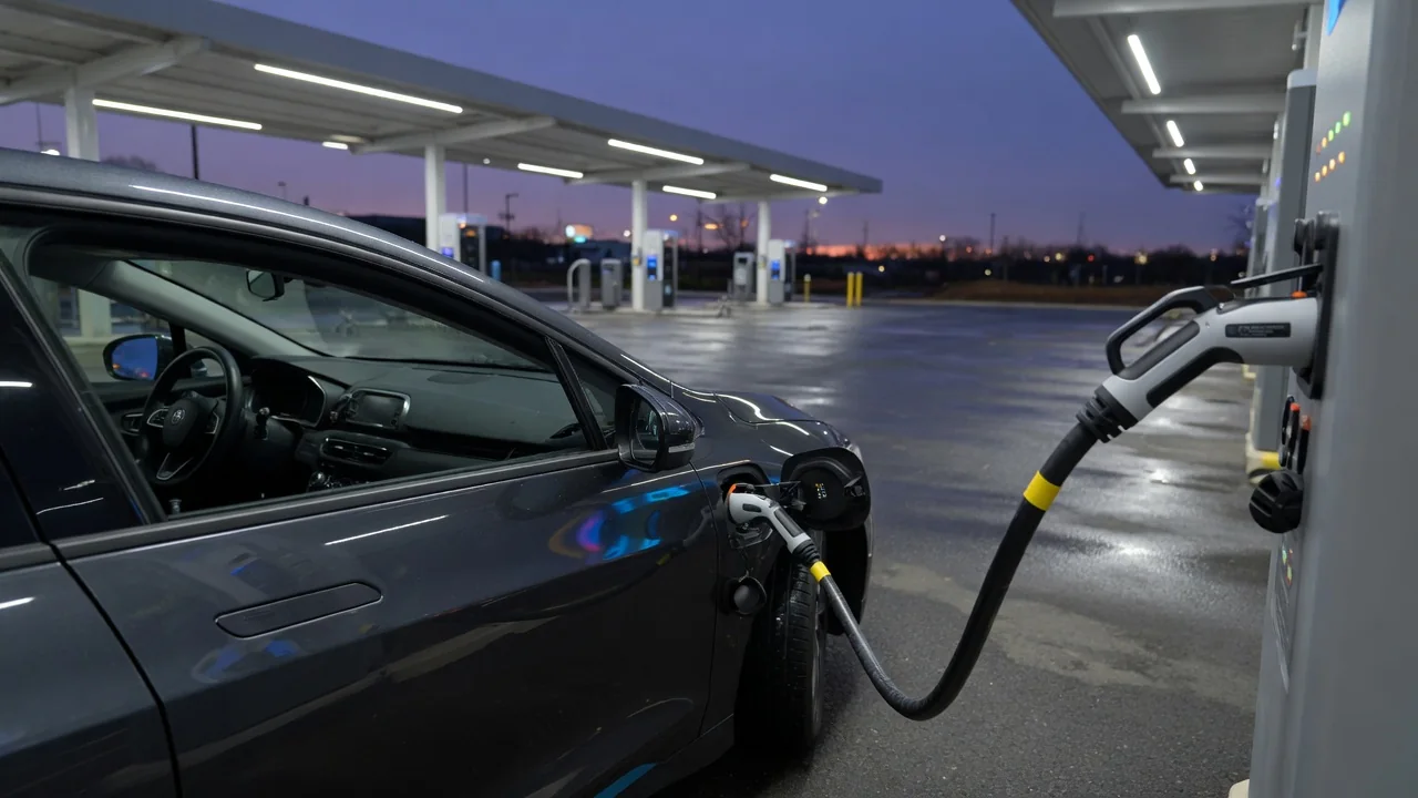
Plugging in an electric vehicle looks like a purely mechanical act, but a short exchange of electrical signals and, on many chargers, digital messages decides whether any energy flows at all. This EV charger vehicle communication confirms the plug is seated and safe, settles how much power the car can accept, and keeps watching until the session ends. Here is what happens in the EV charging handshake, step by step, and where vehicle-specific behavior takes over from the general standard.
Connection check
Before any high-power contact is energized, the charger and vehicle verify that a real, intact connection exists. In the widely used AC charging scheme defined by SAE J1772 in North America and IEC 61851 internationally, this starts on two low-voltage signal lines that sit alongside the power pins: the control pilot and the proximity circuit. The power pins stay dead during this phase. Chargers keep their output contactors open until the signal checks pass, so a connector that is not plugged into a car is not supposed to carry line voltage.
The proximity circuit tells the vehicle that a connector is present. In the J1772 connector, a resistor network combined with the latch button lets the car detect insertion and notice when the release is pressed, which many vehicles use to reduce or stop current before the plug is pulled. On Type 2 connectors used in Europe, a resistor value in the cable also signals the cable's current rating, so the system does not push more current than the cord is built for.
The control pilot does the rest of the early work. The charging station places a nominal 12-volt signal on the pilot line. When the vehicle is connected, a resistor in the car pulls that voltage down to about 9 volts, telling the station a vehicle is present but not yet asking for energy. The pilot circuit relies on the protective earth conductor to complete its loop, so a missing ground connection prevents the normal states from appearing. Stations typically run self-checks of their own, such as ground-fault monitoring, before moving on.
Power agreement
For AC charging, the power agreement is surprisingly simple. Once the vehicle is detected, the station switches the pilot to a 1 kHz square wave, and the duty cycle of that wave advertises the maximum current the station can supply. The vehicle's onboard charger reads this value and limits its draw to the lowest of the station's offer, the cable rating where the connector reports one, and its own hardware capability. When the car is ready, it switches in another resistor, pulling the pilot to roughly 6 volts. The station interprets this as a request for power and closes its contactors. A roughly 3-volt state exists for vehicles that require ventilation, which modern battery packs generally do not.
DC fast charging needs a richer conversation because the off-board charger, not the car, converts grid power and must deliver exactly the voltage and current the battery can accept. With CCS, and with SAE J3400 connectors that use the same communication approach, the station sets the pilot duty cycle to about 5 percent to signal that digital communication is required. Power-line communication modems then exchange messages over the pilot wire, following DIN SPEC 70121 or ISO 15118. After the modems pair through a process called SLAC, the two sides set up a session, discover available services and payment options, and swap charging parameters: the station's voltage and current limits and the vehicle's maximum voltage, current, and target values. CHAdeMO reaches a comparable agreement over a CAN bus rather than power-line communication.
Before the main current flows, two safety steps typically take place. In the cable check, the charger applies voltage to the DC output and tests insulation resistance to confirm there is no fault between the conductors and the chassis. During precharge, the charger raises its output to match the battery's present voltage so that when the vehicle closes its own contactors there is no large inrush current. Where ISO 15118 Plug & Charge is supported by both the car and the network, authorization can also be handled automatically through digital certificates exchanged during the session, instead of an app or card.
Session monitoring
The handshake does not end when energy starts flowing. During DC charging, the vehicle's battery management system sends a steady stream of current demand messages, updating its requested current and voltage as cell temperatures, state of charge, and internal limits change. The charger answers each message with its present output voltage and current and whether it is hitting any of its own limits. If messages stop arriving within the timeouts defined by the protocol, the charger is expected to shut down its output. Insulation monitoring usually continues throughout the session, and stations also track connector and cable temperatures, reducing power if components run hot.
On AC charging, monitoring stays at the analog level. The station keeps watching the pilot voltage; if it drops out of the expected range, rises back toward 9 or 12 volts, or shows a fault condition, the station opens its contactors. The station can also change the PWM duty cycle mid-session to lower or raise the allowed current, which is how some load-management systems share capacity between several chargers. The vehicle then adjusts its draw to the new limit.
Ending a session is a handshake in reverse. When the battery reaches its target, the driver stops charging, or a fault occurs, the side that initiates the stop signals it, current ramps down, and contactors open. In DC charging, the vehicle typically performs a welding detection step, checking that its contactors actually opened and did not fuse together, before the connector lock releases.
Practical implications and limits
Understanding the sequence helps explain common charging behavior. A session that never starts usually failed at a specific stage: the connector was not fully latched, a damaged pin or dirty contact disrupted the pilot signal, the communication modems failed to pair, or the cable check detected an insulation problem. Reseating the connector, trying another stall, or restarting the session from the vehicle or station often clears transient faults, because each attempt runs the full handshake from the beginning. Repeated failures on one station but not others point toward the equipment; failures across many stations point toward the vehicle's inlet, wiring, or software.
The handshake also explains why advertised charger ratings rarely match what a car receives. The negotiated current is always capped by the weakest participant, and during DC charging the vehicle continuously lowers its requests as the battery fills or as temperature moves outside its preferred range. A high-power station cannot force more energy into a car that is not asking for it. Adapters must preserve both power and signal paths; an adapter that mishandles the pilot or proximity lines may prevent charging entirely or limit the session.
The standards define messages and safety boundaries, but they leave much to manufacturers. Requested current curves, timeout tolerances, how a car reacts to a lost signal, Plug & Charge availability, and supported protocol versions all vary by vehicle, software release, and charging network. Compatibility issues between particular cars and stations are often addressed through software updates on either side. For model-specific charging limits or error codes, the vehicle's owner's manual and service information remain the authoritative references.