Wastegate Actuator Replacement: Procedure and Setup Requirements
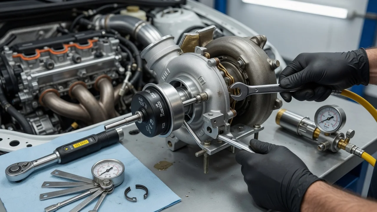
A wastegate actuator opens the turbocharger wastegate to limit boost pressure. When it fails, the engine may underboost, overboost, show warning lights or lose power. On some engines a turbo wastegate actuator replacement is a few bolts and a clip. On others it requires turbo removal or electronic calibration. This guide covers confirming the diagnosis, preparing the job, removal, installation and setup, and final checks. Exact steps and settings must always come from the service information for your vehicle configuration.
Confirm the part and repair scope
Wastegate actuators come in three broad types. Pneumatic units are operated by boost pressure. Others are operated by vacuum. Electronic actuators use a motor and position sensor controlled by the engine computer. The same engine family can use different turbochargers across model years, markets or power outputs. Identify the correct actuator by VIN, engine code and the part number on the turbocharger or actuator, not by appearance alone. Electronic actuators may differ in connector, calibration or software, even when they look identical. Some manufacturers supply the actuator only as part of a complete turbo assembly, which changes the scope of the job considerably.
Before buying parts, make sure the actuator is actually at fault. Many boost complaints come from elsewhere: a split vacuum or pressure hose, a faulty boost control solenoid, a charge air leak, a sensor fault, or a wastegate flap that is seized or has a worn pivot. A new actuator will not cure a binding or rattling wastegate. A basic inspection starts with the engine cold. For pneumatic units, apply pressure or vacuum with a hand pump, as appropriate for the type. Check that the rod travels smoothly and that the diaphragm holds without leaking down. For electronic actuators, compare commanded and actual position with a scan tool and run any available actuator test. Check the service history too, because a previous replacement or adjustment can explain a change in behavior.
Prepare tools and safe access
Obtain the manufacturer procedure for your exact engine before starting. It tells you whether the actuator can be reached in place or the turbocharger must come off. It also lists any parts to be replaced rather than reused, the fastener torque values, and any adjustment or calibration needed afterward. Typical tools include a socket set, a torque wrench, penetrating oil, a hand pressure or vacuum pump, and pliers suited to the retaining clip. Have new clips, gaskets or fasteners ready where the procedure specifies them. Electronic actuators usually need a scan tool that can perform the relevant learn or calibration function. Confirm that capability before you disassemble anything.
Turbochargers and exhaust components stay hot long after shutdown, so work only on a fully cooled engine. If access is from below, support the vehicle on rated stands on level ground. Disconnect the battery when the service information calls for it, particularly before unplugging an electronic actuator. Some situations suit a professional workshop rather than an inexperienced owner. These include jobs that require turbo removal, disconnection of oil or coolant lines, or calibration with equipment you do not have. An incorrectly set actuator can allow uncontrolled boost and damage the engine.
Remove without avoidable damage
The exact sequence depends on the engine, but a pneumatic actuator removal generally follows a common pattern. First remove any heat shields or components blocking access. Label and disconnect the pressure or vacuum hose. Then release the retaining clip that holds the actuator rod to the wastegate lever, and unbolt the actuator from its bracket on the turbocharger. With an electronic actuator, you typically unplug the connector, release the linkage and remove the mounting fasteners. Photograph hose routing, connector positions and bracket orientation before taking anything apart. On adjustable units, note how far the rod is threaded, for reference only.
Fasteners on the hot side often seize. Apply penetrating oil, allow it time to work and use steady force, because a snapped bolt in a turbine housing turns a simple repair into a major one. Do not pry against the wastegate lever or bend it, and keep small clips away from open intake or exhaust passages. While the actuator is off, move the wastegate lever by hand. Excessive play, roughness or binding points to a turbocharger problem that the new actuator will not correct.
Install and restore the system
Mount the new actuator in the same orientation as the original, with the hose port or connector facing its original direction. The rod should line up with the wastegate lever without being forced sideways, since side load causes premature wear. Tighten the mounting fasteners to the manufacturer specifications. Fit a new retaining clip at the lever and confirm that it is fully seated. A loose clip can let the rod detach, leaving the wastegate uncontrolled.
Setup requirements vary. Adjustable pneumatic actuators have a rod length or preload setting that must be made according to the service information. This may involve a measurement taken with a specified pressure or vacuum applied. Do not simply copy the old rod position, because the original setting may have drifted or been altered. Non-adjustable or factory-preset units should not be modified. Many electronic actuators need an end-stop learn or calibration through a scan tool after fitting. Without it, the system may set fault codes or control boost incorrectly. Finally, reconnect hoses, connectors and heat shields, and restore battery power if it was disconnected.
Check the completed work
Before starting the engine, confirm that every hose is secure and the clip is locked. Make sure no wiring or hose can touch hot exhaust parts. On a pneumatic unit, use the hand pump again to check that the rod moves smoothly and returns fully. On an electronic unit, confirm that the calibration completed successfully and run the actuator test if available. Record any stored fault codes, then clear them.
Road test with a scan tool connected and compare desired and actual boost and, where reported, actuator position. Test under the operating conditions described in the service information. Overboost warnings, slow boost build, reduced power mode, hissing, rattling or an exhaust smell all call for further diagnosis. Likely causes include leaks, the control solenoid, sensors or the turbocharger itself. Once the repair is confirmed, record the part number, any adjustment or calibration performed and the date in the service history. Inspect the actuator, hose and clip again during routine work in your maintenance schedule.