Turbo Boost Control Position Sensor: Identification and Function
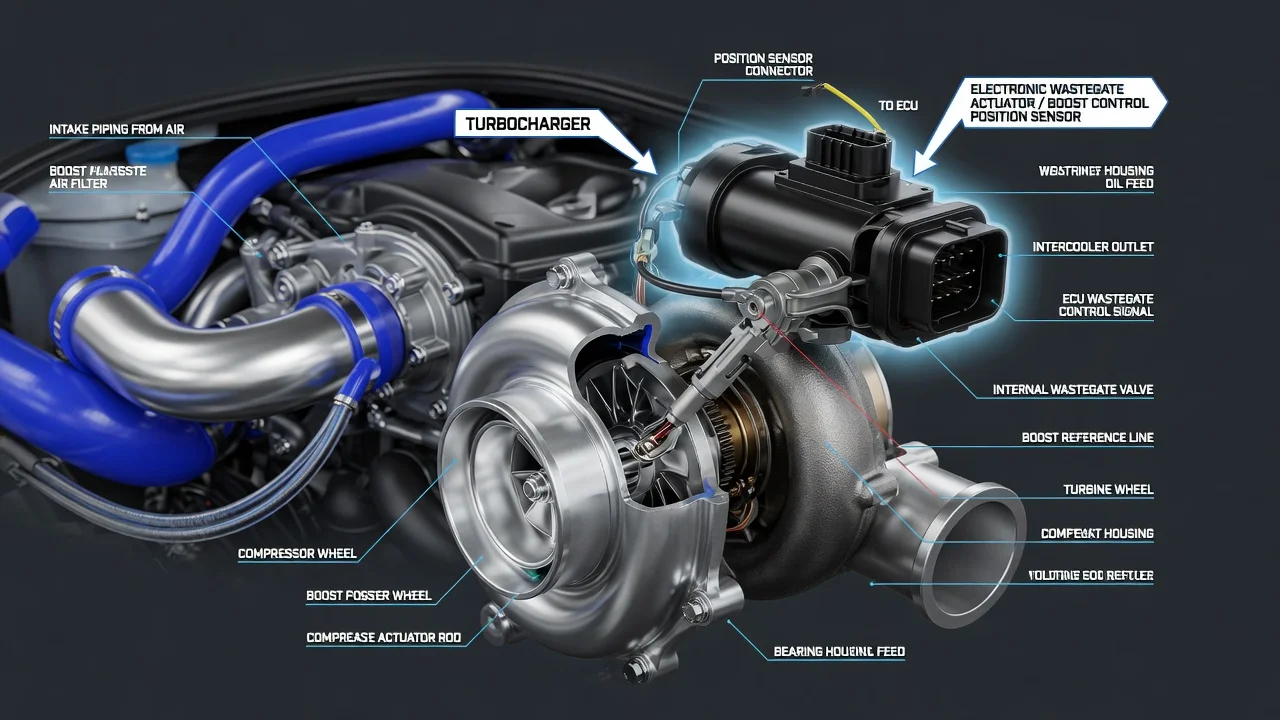
A turbo boost control position sensor tells the engine computer where the turbocharger's boost control mechanism actually is, not just where it was told to go. On modern turbocharged gasoline and diesel engines, including many Volkswagen and Audi models, this feedback is central to accurate boost regulation. This guide explains how to identify the sensor, what it does, why its behavior differs between engines and what an owner can sensibly check before deciding on a repair.
What the boost control position sensor is and does
The turbo boost control sensor is a position feedback device. It measures the physical position of whatever regulates boost on a given engine. On many gasoline engines that is a wastegate flap, which lets exhaust bypass the turbine. On many diesels it is the vane mechanism of a variable geometry turbocharger, which changes how exhaust gas is directed onto the turbine. The engine control module compares the reported position with the position it commanded and with measured boost pressure. If they agree, boost is controlled smoothly. If they disagree and the mismatch persists, the module typically stores a fault code, turns on the check engine light and may limit power to protect the engine and turbocharger.
This part is easy to confuse with the boost pressure sensor. The pressure sensor measures air pressure in the intake tract; the position sensor measures mechanical position at the turbo. Generic diagnostic codes P2562 through P2565 refer to the turbocharger boost control position sensor A circuit, covering a general circuit fault, a range or performance problem, a low input and a high input. Manufacturers may use different names in their service information. On VW models, for example, the sensor is usually described as part of the charge pressure actuator or positioner, and the exact component, location and part number depend on the engine code rather than the model name alone.
How the sensor and actuator work together
Most current designs use a non-contact sensor, often of the Hall-effect type, that reads a magnet or target attached to the actuator rod or shaft. The control module supplies the sensor with a reference voltage and ground, and the sensor returns a signal that changes as the rod moves. The module translates that signal into a position, usually shown in scan tool data as a percentage or in another manufacturer-defined unit. Because the module relies on this signal to close the control loop, a sensor that reads incorrectly can cause underboost or overboost even when the turbocharger itself is healthy.
The actuator that moves the mechanism comes in two broad forms. A vacuum diaphragm actuator is controlled by a solenoid valve, and its position sensor may be mounted on the actuator or attached to it as a separate part. An electric actuator contains its own motor, and the position sensor is commonly built into the same housing. On many VW and Audi engines with an electric boost actuator, the sensor is not serviced separately, so a confirmed sensor fault means replacing the actuator assembly. Many systems also learn the actuator's end positions, and after replacement a basic setting or adaptation with a suitable scan tool is typically required.
What changes the answer for your engine
Vehicle configuration matters more than the badge on the car. A gasoline engine with an electric wastegate actuator, a diesel with a vacuum-controlled variable geometry turbo and a diesel with an electric vane actuator all use the same generic sensor name but behave differently, fail in different ways and require different procedures. The same model and year can be sold with several engines, so identify the engine code and, ideally, use the VIN when looking up parts or service steps for a VW turbo boost control position sensor or any other make.
Operating conditions also shape the result. The sensor lives near the turbocharger, where heat cycling can degrade wiring, connectors and electronics over time. On diesels, soot and carbon can make variable vanes stiff or sticky, especially with frequent short trips, and the sensor then correctly reports that the mechanism is not reaching its commanded position. Worn wastegate linkages, binding pivots, vacuum leaks and a weak solenoid valve can produce the same kind of code. In other words, a fault code naming the position sensor shows where the module saw a problem, not proof that the sensor itself has failed.
What the owner can check and do
Start with symptoms and circumstances. Typical signs include a check engine light, reduced power or limp mode, hesitation under load and, on some gasoline engines, a rattle from a worn wastegate linkage. Note when the problem appears: on a cold start, after a long highway run, under hard acceleration or at random. Read and record the codes along with freeze frame data before anything is cleared, because that snapshot of engine speed, load and temperature is valuable to whoever diagnoses the fault. Clearing codes repeatedly without a diagnosis only hides useful information.
With the engine off and fully cooled, a basic visual inspection is reasonable. Check that the connector at the actuator or sensor is fully seated and not corroded, that the wiring is not melted, chafed or resting against hot parts and, on vacuum systems, that the hoses are intact and properly connected. Review the service history for previous turbocharger or actuator work, related recalls or software updates. If you have a scan tool that shows live data, compare commanded and actual position: a reading that follows the command smoothly points away from the sensor, while a signal that is stuck, jumps or drops out suggests a wiring or sensor issue. Interpret those readings only against manufacturer specifications, and avoid buying parts on a guess.
Limitations and when to get professional help
Signal values, test procedures and adaptation steps differ between manufacturers and engines, so there is no universal reading that proves a sensor good or bad. The position sensor is also not a routine wear item with a set replacement interval in a typical maintenance schedule; it is replaced when diagnosis confirms a fault. Accurate testing usually requires vehicle-specific wiring diagrams and specifications, and actuator replacement on many engines requires a scan tool capable of running the correct adaptation.
Seek professional inspection if the engine stays in limp mode, the code returns after clearing, the actuator needs replacement or adaptation, or you suspect a mechanical turbo problem such as sticking vanes or a damaged wastegate. A persistent boost control fault can lead to poor performance or, in some cases, uncontrolled boost, so drive gently and arrange diagnosis promptly. Bringing the stored codes, freeze frame data and a clear description of when the symptoms occur will help a technician reach the cause faster and avoid unnecessary parts.