Transmission Valve Body Solenoid Replacement
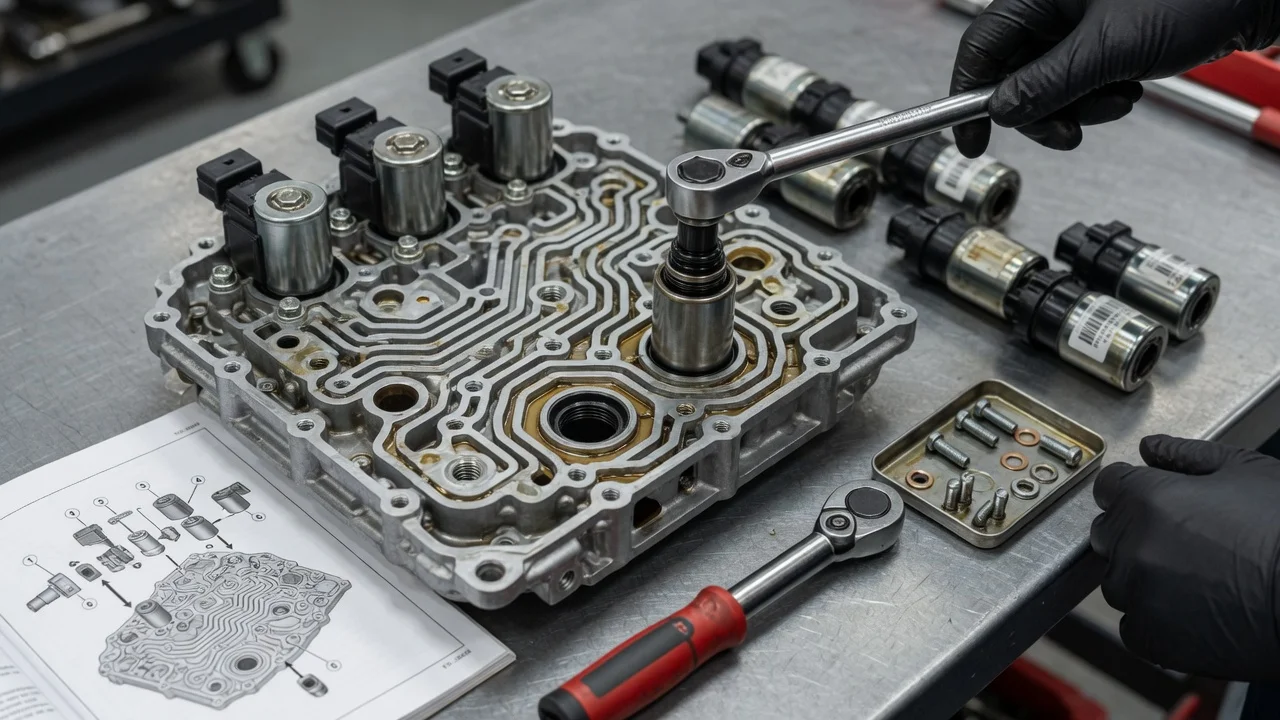
A faulty shift solenoid, pressure control solenoid or torque converter clutch solenoid can cause harsh shifts, slipping, a stuck gear or a warning light. Replacing one is usually far less work than overhauling the transmission, but the job differs widely between designs. Some solenoids come out once the pan is off. Others are built into a valve body or a mechatronic unit that needs programming. The steps below cover confirming the fault, preparing, removing and installing the part, and checking the result.
Confirm the part and repair scope
Diagnostic codes describe what the control module detected, not which part failed. A solenoid circuit code can come from a damaged harness, a corroded or loose connector, a failed internal wiring pass-through or a module fault, as well as from the solenoid itself. A performance or gear ratio code can result from low or degraded fluid, a restricted filter, sticking valves or worn clutches. Before ordering parts, check fluid level and condition using the procedure for that transmission. Review freeze frame data, and inspect the wiring and connectors. Measure solenoid circuit resistance against the published range, and use a scan tool to command the solenoid if the vehicle supports it. Shift behavior that matches the code supports the diagnosis but does not prove the solenoid is the cause.
Fitment depends on the exact transmission, not just year, make and model, because one model may use more than one transmission type. Use the identification tag on the case or a VIN-based parts lookup. Find out whether your unit uses individual solenoids, a solenoid pack, or a valve body assembly or mechatronic unit with an integrated control module. Service history also matters. Overdue fluid changes, earlier repairs or a rebuilt unit can change the likely cause. If the fluid smells burnt or carries heavy friction material, or clutch slip codes are present, a solenoid alone is unlikely to fix the problem. Depending on findings, repair options include a single solenoid, a solenoid pack, a complete valve body, a remanufactured transmission or a professional repair.
Prepare tools and safe access
Get the factory service information for your exact transmission before starting. It gives the removal procedure, bolt locations and lengths, torque values and tightening sequence, the fluid specification and the fill and level check method. The fluid specification is not optional. The wrong fluid can change friction behavior and shift quality and may cause damage. Typical needs include a lift or properly rated jack stands on level ground, wheel chocks, a large drain pan, and a torque wrench that reads accurately in the low range valve body bolts usually require. You will also need the right sockets, a new pan gasket or the specified sealant, a filter if the procedure calls for one, lint-free cleaning materials and a scan tool with transmission functions.
Let the transmission cool, because hot fluid can cause burns. Disconnect the battery if the procedure requires it, and clean the outside of the pan area so dirt cannot fall inside. Some of this work is not suited to inexperienced owners. Removing a valve body can release check balls and springs that must go back in exact positions. Mechatronic units often need dealer-level software for programming. Many modern transmissions, including some CVTs and dual clutch units, need fluid at a specific temperature read on a scan tool for an accurate level check. If you cannot carry out a required step, plan for a shop to finish the job.
Remove without avoidable damage
The general sequence is to raise the vehicle level, drain the fluid, then remove the pan and filter if needed. Note how much fluid comes out and look at it and the pan magnet. Fine gray paste is common, but metal chunks or a lot of friction material point to wear beyond a solenoid. Release electrical connectors by their locking tabs rather than pulling on wires, since aged plastic breaks easily. Individual solenoids are often held by a clip, bracket or single bolt. If the valve body has to come out, photograph or mark each bolt location, because lengths usually differ and a bolt in the wrong hole can damage the case or bottom out. Support the valve body as the last bolts come free, and expect more fluid to drain.
Keep the valve body flat so check balls and the separator plate stay in place, and compare their positions with the service manual before going further. Never pry against valve body mating surfaces or solenoid bodies. Watch the manual valve link and any internal harness connectors as the assembly drops. Do not take the valve body apart unless the procedure calls for it. Lay parts on a clean surface and cover open passages, because small particles can cause valves to stick.
Install and restore the system
Compare the new solenoid with the old one before installing it, including connector shape, mounting style, port layout, O-rings and any identification marks. Coat O-rings with the specified transmission fluid so they seat without tearing. Fit each solenoid in the same orientation as the original, with connectors aligned and wiring routed clear of moving parts and the pan. When reinstalling a valve body, confirm check balls and the separator plate are positioned correctly. Engage the manual valve with its linkage, then start every bolt by hand in its marked location. Tighten in the specified sequence to the specified torque, because overtightening can distort the valve body and cause valves to bind. Fit the new filter and gasket, and torque the pan bolts to specification.
Refill with the specified fluid and follow the exact level check procedure. Depending on the unit, that may mean the engine running, the selector cycled through each position and a set temperature range, checked at a dipstick or fill plug. Then complete any commissioning steps in the instructions. These can include clearing codes, resetting adaptive values, entering calibration or identification data supplied with a solenoid pack, programming a replacement valve body or mechatronic unit, and running a guided relearn or adaptation drive.
Check the completed work
Inspect the pan, plugs and lines for leaks, and recheck the fluid level once the transmission reaches the temperature the procedure specifies. Scan for codes, then watch live data where available, such as commanded versus actual gear, solenoid status, line pressure and torque converter slip. Road test cold and again fully warm. Check engagement into drive and reverse, light and firm throttle upshifts, coasting and passing downshifts, and converter clutch lockup at steady cruise. Some shift feel can keep improving as the module relearns over normal driving, so follow any recommended adaptation routine before judging the result.
Some signs call for more diagnosis rather than another part. These include the original code returning quickly, new codes appearing, delayed engagement, flare between gears, slipping, harsh shifts that remain after adaptation, or fresh debris in the fluid. A circuit code that returns usually points back to wiring, connectors or the control module. Persistent ratio or slip faults suggest mechanical wear or a valve body problem. Record the parts, fluid and procedure used in the vehicle service history so later diagnosis starts from accurate information.