Transmission Valve Body Repair: Options and Repair Process
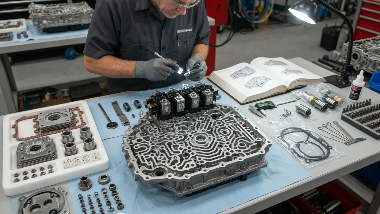
The valve body is the hydraulic control center of an automatic transmission. It routes pressurized fluid to the clutches and bands that select each gear. Repairing it can solve real shift problems. However, many complaints that look like valve body trouble come from low or degraded fluid, solenoid or wiring faults, software issues or internal clutch wear. This guide explains how to confirm the fault, define the scope, choose a repair option and verify the result.
Confirm the fault before repair
Start with the basics. Check the fluid level and condition using the manufacturer's procedure, since many units must be checked at a specific temperature and with a specific method. Confirm that the fluid matches the required specification, and review the service history for recent fluid changes, previous repairs or software updates. Next, scan the transmission control module for diagnostic codes, not only the engine module. Solenoid circuit, pressure control, gear ratio and slip codes all point to different paths. A gear ratio code records what the transmission did. It does not tell you why it did it.
Note the exact shift behavior: harsh or delayed engagement, flare between gears, slipping that appears only when warm, or a transmission locked in one gear in a failsafe mode. These symptoms overlap with worn clutches, a weak pump, torque converter faults, damaged connectors and control module problems. Useful evidence includes live data comparing commanded and actual gear, slip values and solenoid commands. It also includes mechanical pressure readings at test ports where the unit provides them and electrical tests of solenoid circuits against service specifications. Inspect the pan and filter as well. Heavy friction material or metal debris suggests wear beyond the valve body.
Treat a valve body fault as confirmed only when several things line up. The pressure or shift fault should follow a pattern explained by a specific hydraulic circuit. Electrical causes should have been ruled out. The clutches should hold when they receive correct pressure. Some transmissions are known for valve bore wear, but a known pattern is still a hypothesis until testing supports it.
Define the repair scope
Identify the transmission type and the exact unit, using the identification tag, model code and vehicle build data. Valve bodies can differ by model year, engine, drivetrain and calibration, even within one transmission family. Fitment therefore matters as much as the part name. The configuration also changes the job. Some designs have solenoids bolted to the valve body. Others use a separate solenoid pack. Many dual-clutch and some modern automatic units combine the hydraulic control and the control module in one mechatronic assembly. Continuously variable transmissions use their own valve body designs and procedures.
Determine the extent of the damage. A fault may be isolated to one circuit, such as a sticking valve, a worn bore, a failed solenoid, a damaged separator plate gasket or a missing check ball. Alternatively, the valve body may be a victim of contamination from a failing clutch pack or pump. In that case, a new valve body will pick up the same debris and the original cause will remain. Include the filter, the fluid and the cooler and lines in the scope, because debris trapped there can return to the hydraulic system.
Compare repair options
On some electronically controlled transmissions, harsh or erratic shifts after a battery disconnect or fluid service respond to an adaptive reset, a relearn procedure or a manufacturer software update. This is the least invasive option when the evidence points to calibration rather than hardware. It will not correct mechanical wear, and it can temporarily mask wear by compensating for it.
Component repair targets the confirmed defect. Examples include replacing a solenoid, separator plate gaskets or check balls, or reaming worn bores and fitting oversized valves from purpose-made kits. This keeps the original part that matches the vehicle's calibration. It requires precision, cleanliness and knowledge of that valve body's layout, and it leaves undiagnosed wear in other bores untouched. Replacing the whole valve body with a new or remanufactured unit avoids internal rework. It still depends on exact fitment and may require solenoid data entry, coding or programming, especially for integrated mechatronic units. Neither approach repairs clutches, the pump, the converter or wiring.
Choose specialist service or an overhaul when testing shows contamination, internal clutch damage or a fault that the valve body cannot explain. In those cases, valve body work alone leaves the root cause in place, and a rebuilt or replacement transmission is usually the more realistic option. Specialist shops can also bench test valve bodies and program integrated units. Compare warranty terms as well as price, because they often differ between repair options.
Requirements and limits
Valve body work requires service information for the exact unit. That includes the removal steps, bolt locations and lengths, torque values and tightening sequence, check ball positions and the fluid fill and level check procedure. Valve body bolts often differ in length, and putting one in the wrong hole can damage the case or leave a section under-clamped. You also need a scan tool that can read transmission data and run relearns, and programming access where the unit requires it. The work area and tools must be clean, because small particles can make a valve stick.
Support the vehicle safely on a lift or rated stands, and keep it level for the fluid check. Hot fluid can cause burns, so let it cool before draining and handle it carefully. Follow the electrical disconnection steps in the service information, and dispose of used fluid properly. Never mix fluid types; use only the specified fluid. An owner can reasonably check fluid, read codes and record symptoms. Pressure testing, bore machining and programming integrated units are generally specialist tasks. Disassembling a valve body without the correct information and tools risks misassembly that is harder to diagnose than the original fault.
Verify the outcome
After the repair, fill and check the fluid at the specified temperature, inspect for leaks, clear the codes and complete any required relearn. Then road test the vehicle from cold to fully warm. Cover every gear, light and heavy throttle, reverse engagement, coast-down shifts and manual mode if the vehicle has one. Watch live data for slip and for agreement between commanded and actual gear. Recheck the fluid level after the drive.
Record the codes before and after the repair, the part numbers, any software or calibration changes, the fluid used and the quantity, any pressure readings and the road test results. This record supports warranty claims and makes future diagnosis faster. If the original symptom persists, do not keep replacing parts. Go back to the diagnosis: wiring and connectors, the control module, pump pressure, clutch condition and the torque converter. An unchanged fault after a verified valve body repair means the original conclusion was wrong or incomplete. If the work is under warranty, return the vehicle to whoever performed it.