Transfer Case Shift Motor Wiring Diagram: Identifying Circuit Connections
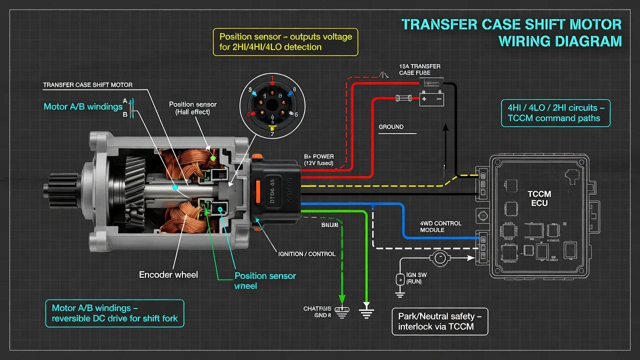
A transfer case shift motor wiring diagram shows how the shift motor, its position feedback circuits and the control module connect. Reading it correctly can save you from replacing a motor that was never the problem. This guide explains the circuits you will usually find, how they behave, and how to check them safely on the low-voltage system without guessing at pin numbers or wire colors.
What the shift motor diagram shows
Most electronically shifted transfer cases use a shift motor, sometimes called an encoder motor or actuator, commanded by a transfer case control module or by a function built into another module. The wiring generally falls into two groups. The first is the motor drive pair: two wires that carry current to the motor windings. The module reverses polarity on this pair to turn the motor in either direction, so neither wire is a permanent power feed or a permanent ground. The second group reports position back to the module, either as several encoder contact lines or as a position sensor with a reference voltage, a signal and a ground. Some designs add a separate circuit for a motor brake or lock.
Pin numbers, wire colors, connector views and circuit identifiers vary by manufacturer, model year and transfer case version. The only reliable way to identify a specific terminal on your vehicle is the factory wiring diagram for that exact build. Use the general layout described here to understand what you are looking at, not to assign a function to a particular pin.
How the shift motor circuit works
When you select a new mode with the switch or dial, the module checks its required inputs, which can include vehicle speed, transmission range and brake status depending on the design. If conditions are met, it energizes the motor drive circuits. Current flows through the motor in one direction to move toward one mode and in the opposite direction to move back. Inside the case, the motor turns a shift shaft or cam that moves the shift mechanism.
The position circuits tell the module when the motor has reached the requested position. On encoder-style motors, contacts on a moving plate connect different combinations of circuits, and the module reads that pattern as a position. On sensor-style motors, the module supplies a reference voltage and reads a signal that changes as the shaft turns. If the reported position does not match the command within the expected time, the module typically stops driving the motor, flashes the mode indicator and may store a diagnostic trouble code.
The module itself is powered from the starter battery through fused circuits, commonly a constant feed and an ignition-switched feed, plus one or more grounds. A blown fuse, a corroded ground or excessive voltage drop on these feeds can produce the same symptoms as a failed motor, which is why the power side of the diagram deserves as much attention as the motor connector.
What changes the answer for your vehicle
Configuration matters. Part-time, full-time and on-demand systems use different control logic, and some drivetrains have no separate shift motor because actuation is handled another way. The control function may live in a dedicated module or inside another one, so the motor wires can lead somewhere you would not expect. Connector locations differ as well: the motor plugs in at the transfer case, while the module may sit under the dash, behind a trim panel or elsewhere on the vehicle.
Operating conditions also affect what you measure. Many systems only allow a range shift with the vehicle stopped or below a set speed, often with the transmission in neutral and the brake applied. Testing without meeting those conditions can look like a dead circuit when the module is simply refusing the request. Low system voltage is another factor, since a weak battery or poor charging output can cause the module to abort a shift partway through.
Hybrid and electrified four-wheel-drive vehicles need extra care. Where a shift motor is used, it is normally part of the low-voltage system fed by the starter or auxiliary battery, not the high-voltage traction battery. These vehicles still carry high-voltage cables, usually orange, and high-voltage components that may run near the driveline. Disconnecting the 12-volt battery does not by itself make the high-voltage system safe. Follow the manufacturer's high-voltage isolation procedure before working near those components, and never probe orange cables or high-voltage connectors.
Checks an owner can make
Start with the basics. Confirm battery condition and measure system voltage at the battery terminals with the engine off and running to check charging output. Locate the relevant fuses in the diagram and inspect them; replace a blown fuse only with one of the same fuse rating, never a larger one, and find out why it blew. With the ignition off, inspect the motor connector at the transfer case. Its exposed location makes corrosion, water intrusion, damaged seals and bent terminals common causes of intermittent faults.
Using the factory diagram, back-probe connectors or use proper breakout leads rather than piercing insulation. Check module power and ground with a voltage drop test under load, since a good open-circuit reading can hide a weak connection. To confirm the module is commanding the motor, a test light or a meter with a min/max function across the drive pair can show a brief output when a shift is requested, then the opposite polarity when shifting back. Do not apply battery voltage directly to motor or module terminals unless the service procedure specifically calls for it, because driving the motor in the wrong direction or past its travel can damage the motor, its position contacts or the module.
For the position circuits, check continuity between the motor connector and the module connector as the diagram shows, and look for shorts to ground or to power. If you also have a battery that runs down overnight, a module that fails to go to sleep can contribute to parasitic draw, but measuring it properly means waiting for the vehicle's modules to shut down before reading current.
Limitations and the next step
This explanation cannot provide pinouts, wire colors, encoder patterns or sensor voltage specifications, because those values are specific to each vehicle and must come from the manufacturer's service information. Without them, you can confirm power, ground, fuses and wiring integrity, but you cannot reliably judge whether a position signal is correct.
A capable scan tool that can read transfer case codes, view position data and command the motor makes diagnosis far more accurate. Some vehicles also require a calibration or relearn after a motor or module is replaced. If the electrical checks pass but the case still will not shift, the fault may be mechanical inside the transfer case. In that situation, or whenever high-voltage components are involved or module programming is needed, take the vehicle to a qualified technician.