Trailer Brake Controller Wiring Diagram: Connections, Colors and Setup Basics
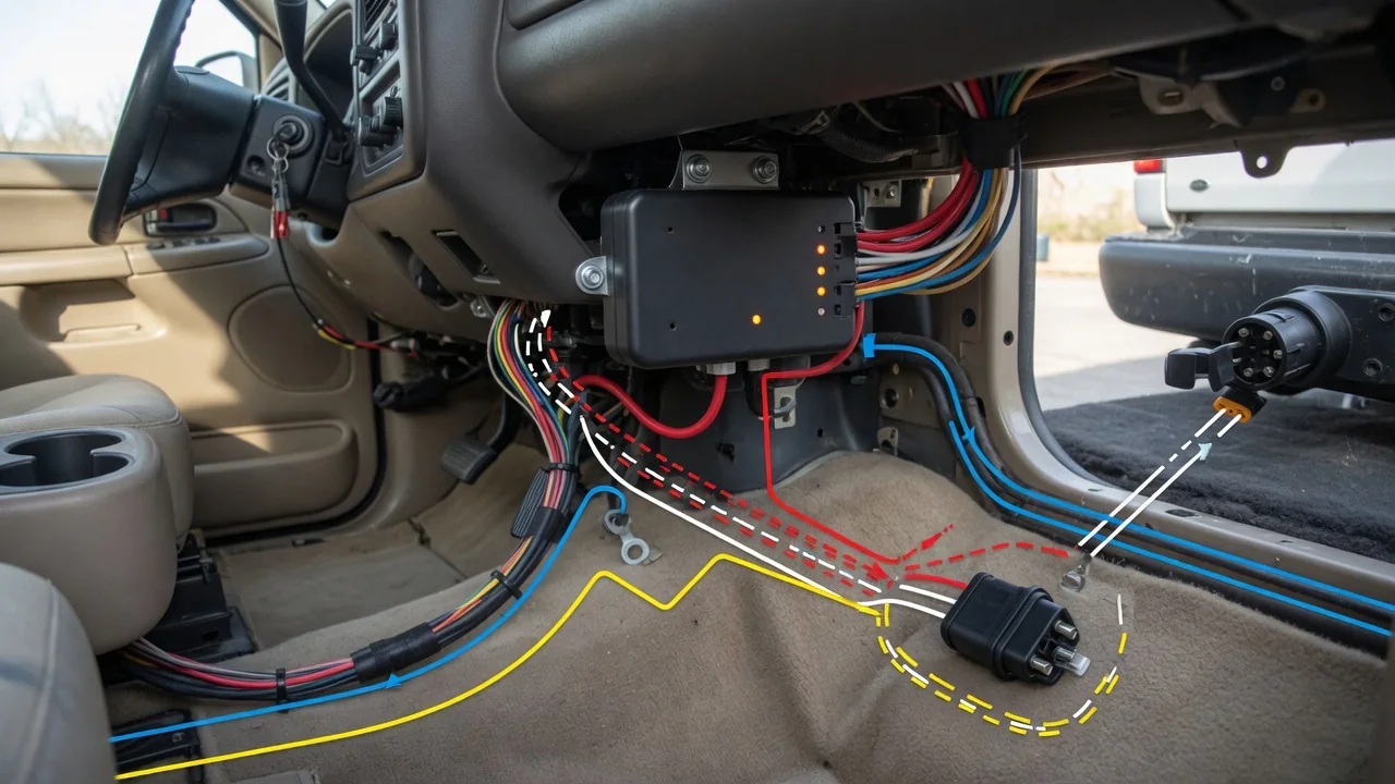
A trailer brake controller wiring diagram shows how a small box under the dash turns your brake pedal input into stopping power at the trailer's wheels. Whether you are learning how to wire a trailer brake controller yourself or want to understand what an installer did, knowing the connections, color conventions and setup basics makes the system less mysterious and safer to use.
How to Read a Trailer Brake Controller Wiring Diagram
A wiring diagram for a trailer brake controller is a connection map. It shows how the controller ties into four things: tow vehicle battery power, a ground, the brake light signal and the electric trailer brakes themselves. Most drawings label a power source with a fuse or circuit breaker beside it, a ground point on the chassis or battery, an input from the stop light switch, and a brake output wire running rearward to the trailer connector.
The words diagram and schematic are used interchangeably here; a trailer brake controller wiring schematic and a trailer brake controller diagram describe the same layout, drawn with more or less detail. Whichever term appears, the instructions supplied with the controller are the authoritative version. Layouts differ by controller brand, vehicle and trailer connector style, so a generic drawing helps you understand the concept but should never be treated as the final word for your setup.
The Core Connections on an Electric Trailer Brake Controller
Every electric trailer brake controller wiring diagram is built around four circuits. Fused battery power supplies the current the controller will send rearward. A chassis ground completes the circuit, and a weak ground is a classic source of erratic braking. The brake pedal signal, taken from the stop light switch circuit, tells the controller that you are braking. Finally, the output circuit carries a variable voltage to the trailer brake magnets, which create the friction that slows the trailer.
Because brake magnets draw substantial current, and more axles draw more, the power and output circuits need wire gauge and circuit protection matched to the controller maker's specifications rather than a rule of thumb. The output usually reaches the trailer through the 7-way trailer connector, and the brake terminal must be identified correctly on both the vehicle socket and the trailer plug. Electric-over-hydraulic trailer brakes may require a compatible controller or additional setup, so confirm compatibility before wiring anything.
Trailer Brake Controller Wire Color Codes and Why They Vary
People searching for a trailer brake controller wiring color code usually find a familiar pattern: a blue wire is often used for brake output, and many aftermarket pigtails follow similar habits for power, ground and the stop light signal. Treat that as a typical convention, not a standard. Controller pigtails, vehicle factory harnesses and aftermarket trailer connectors can each use different colors for the same function, and earlier repairs can scramble things further.
Before connecting anything, confirm each wire's function in the controller manual and the vehicle wiring information, then verify it with a test light or multimeter. A stop light input, for example, should show voltage only when the pedal is pressed, while a ground should show continuity to bare chassis metal. Guessing by color alone carries real consequences: a miswired output can leave the trailer with no brakes at all, and a power wire on the wrong circuit can create a short.
What Wiring In a Trailer Brake Controller Involves
Wiring a trailer brake controller comes down to a few broad stages: choosing a mounting spot where the driver can reach the manual override, finding the connection points, making the connections, and routing and securing the wires. How involved that becomes depends on the vehicle. A plug-in adapter harness matched to the truck joins the controller to an existing factory connector, while a hardwired install means running new circuits to the battery and back to the rear connector.
Anyone asking how to wire in a trailer brake controller should keep several safety points in view. Disconnect power the way the vehicle manufacturer instructs before touching wiring, keep wires clear of exhaust heat, steering components, pedals and other moving parts, and use only the fusing or circuit breakers the controller maker specifies. The controller instructions and the vehicle service information override any general guide, including this one, and anyone unsure about the work is better served by a qualified installer.
Ford and GM Trucks with Factory Brake Controller Provisions
Many Ford and GM trucks ordered with a tow package leave the factory prepared for trailer braking. Some carry a connector tucked behind the dash intended for an aftermarket controller, with circuits to the rear socket already in place; others have a controller integrated into the dash. Which arrangement you have varies by model, year and trim, so two trucks that look alike in the parking lot may be wired quite differently.
Where the factory plug exists, a vehicle-specific adapter harness can link an aftermarket controller to it without cutting wires, though fit has to be checked against the exact model and year. A truck with an OEM integrated controller may not need an aftermarket unit at all, and the owner's manual explains how that system operates. For a Ford trailer brake controller wiring diagram, a Ford OEM diagram or the GM equivalent, rely on the owner's manual, dealer service information or the harness maker's fit guide.
Brand-Specific Diagrams for Reese, Prodigy and Impulse Controllers
A Reese trailer brake controller wiring diagram, a Prodigy diagram and an Impulse diagram all live in the same place: the instructions packed with the controller. That sheet is the reference to follow, because it reflects the connector and wire labeling of the unit in your hands. Even within one brand, designs differ. A proportional brake controller, which senses deceleration, and a time-delayed brake controller, which ramps output at a preset rate, may label wires or connectors differently, so the exact model number matters.
Connector styles are another reason to stay model-specific. The plug or pigtail on the back of one controller may not match another brand's, so a vehicle adapter harness has to suit the controller as well as the truck. Check both ends before buying. If the original instructions are missing, look up documentation by the model number on the housing rather than borrowing a drawing for a similar-looking unit, and confirm any pinout, wire color or feature there before relying on it.
Checking the Installation and When to Get Professional Help
Once installed, a few safe checks show whether the wiring is doing its job. The controller should power on, indicate a trailer connection when the trailer is plugged in, and respond when the brake pedal is pressed or the manual override is applied, all according to the maker's test steps. Gain adjustment and any sensitivity setting are then usually dialed in at low speed in a safe, open area, following the procedure in the controller manual.
Warning signs deserve attention before any trip: no trailer detected, error messages, brakes that grab or fail to apply, blown fuses, or wires and connectors that feel warm. A driveway check can catch loose plugs and corroded terminals, but it cannot measure current draw at each magnet or reveal worn brake assemblies inside the drums. When symptoms persist, a trailer or electrical shop should test the circuits, connectors and brakes directly, since an error message points toward a fault rather than proving which part failed.