Trace Diesel Engine Ignition Switch Wiring for a No-Start
The short answer
On a diesel engine, the ignition switch is a power distributor. It takes constant battery voltage and routes it to different circuits depending on key position: accessories, the run circuit, glow-plug preheat on many diesels, and the starter-control circuit. To trace a no-start, confirm battery voltage arrives at the switch's main input, then confirm it leaves on the correct output in each key position. Next, follow each output to the component it controls. On older diesels with mechanical injection, that component is often a fuel shut-off solenoid. On electronically controlled diesels, it is usually the engine control module and its relays. The first missing voltage tells you which section of wiring or which component to examine.
One qualification matters more than any other. Terminal numbering, wire colours, connector layouts and the number of key positions vary by manufacturer, model year, market and engine generation. This guide explains the common structure and a testing method. It does not supply a pinout for any specific vehicle, and none was available for this article. Confirm the details against the factory wiring diagram for your exact vehicle before probing or modifying anything.
What the switch typically controls on a diesel
Many European and some other manufacturers label circuits using the DIN 72552 terminal convention. Other manufacturers use their own letters, such as B, ACC, IG and ST, or colour codes only. The table below lists the commonly used DIN designations as an orientation aid, not as a guarantee for any given vehicle.
Terminal (DIN convention) | Usual function | Live in which key position; 30 | Constant battery positive feed into the switch | Always; 75 | Accessory circuits | ACC and usually ON; 15 | Switched ignition or run feed: ECU power, shut-off solenoid, gauges, relays | ON and START; 50 | Start signal to the starter solenoid or starter relay | START only; 17 / 19 | Glow-plug preheat feeds on some older diesel switches | Preheat or heat position, where fitted
Diesels differ from typical petrol-engine switches in two ways that matter for a no-start. First, some older diesels have a dedicated preheat position, or a separate preheat circuit, that powers the glow plugs or their relay before cranking. Second, on many mechanical injection pumps the engine runs only while the run circuit holds a fuel shut-off solenoid open. If that feed is missing, the engine can crank normally and never fire. On electronically managed diesels, including common-rail systems, the run feed powers the control module instead. The module then manages fuel delivery, glow plugs and often the starter.
Match the symptom to the circuit
No crank, no click: suspect the start circuit (terminal 50 or its equivalent), the starter relay, a neutral or clutch safety switch, or an immobilizer that blocks cranking. Cranks but will not fire, and the wait-to-start light behaves normally: suspect the run feed to the fuel shut-off solenoid or to the engine control module. Cranks but will not fire, especially when cold, and the preheat light does not behave normally: suspect the glow-plug control circuit or relay. Dashboard stays dark in the ON position: suspect the main feed into the switch, the switch contacts themselves, or a fuse or fusible link between the battery and the switch.
These are diagnostic starting points, not conclusions. Immobilizer behaviour in particular varies widely. Some systems prevent cranking, others allow cranking but block fuel. The vehicle's service information should state which applies.
Tracing the wiring step by step
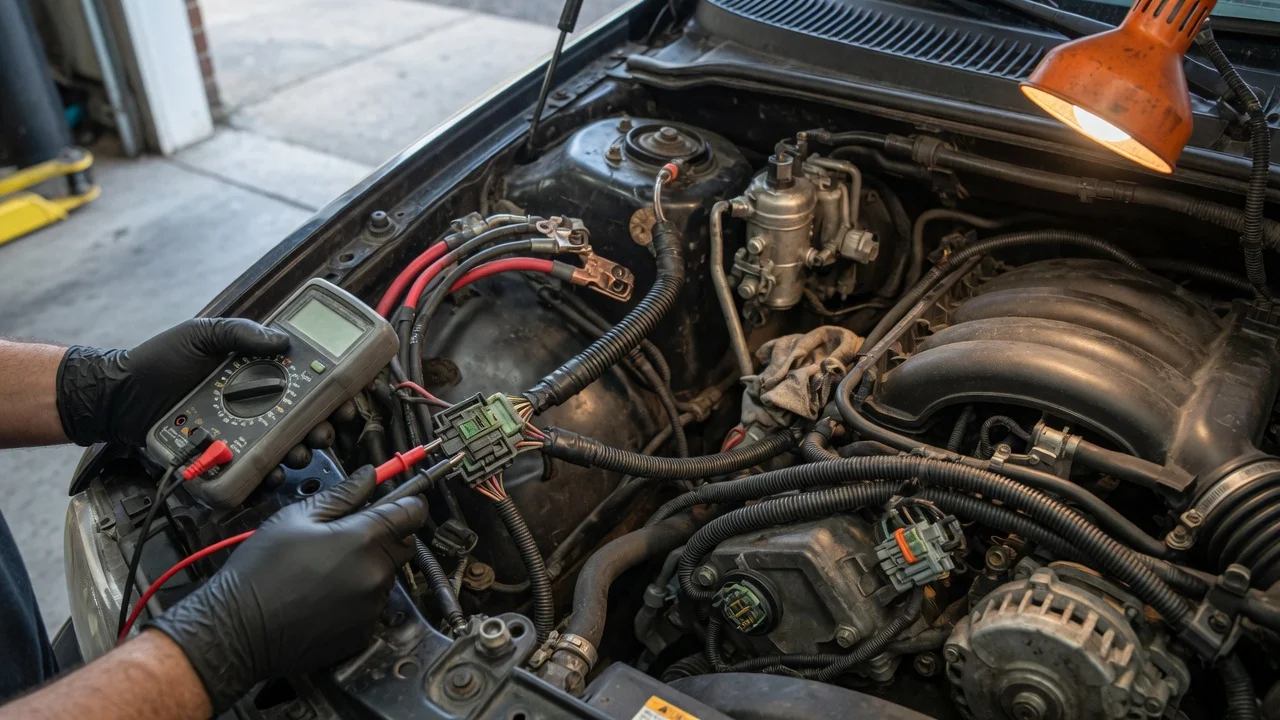
1) Confirm the battery is charged and the terminals are clean and tight. A weak battery can mimic a wiring fault, and diesels draw heavily during preheat and cranking. 2) Identify your system voltage. Most light vehicles use 12 volts, but many heavy trucks and some machinery use 24 volts, so set expectations accordingly. 3) Check the relevant fuses and fusible links between the battery and the ignition switch. 4) Back-probe the switch connector. With the key OFF, the main feed (terminal 30 or its equivalent) should show battery voltage. 5) Turn the key to ON. The run output (terminal 15 or its equivalent) should now show close to battery voltage. 6) If the switch has a preheat position, check that its output goes live when selected. 7) Hold the key in START, or have a helper do so. The start output (terminal 50 or its equivalent) should go live only in this position. 8) If an output is present at the switch, move downstream. Check the same voltage at the shut-off solenoid, the control module power pin, the glow-plug relay or the starter relay, depending on the symptom. 9) Wherever voltage is present at one end of a wire but missing or low at the other, inspect that section for corrosion, broken conductors, chafed insulation or a poor connector.
A plain voltage reading can mislead. A corroded wire may show full voltage with no load connected, then collapse when a solenoid or relay draws current. Where possible, test with the circuit loaded, or perform a voltage-drop test across the wire or switch contact while it operates. The acceptable drop for a given circuit should come from the manufacturer's service information. No specific figure is given here.
Isolating the switch itself
On many vehicles the ignition switch is two parts: a mechanical lock cylinder turned by the key, and a separate electrical switch behind it. A worn electrical switch can lose contact in one position but not another. If voltage enters the switch but fails to leave on the expected output, the electrical switch section is the likely fault. On vehicles with push-button start or keyless systems, there may be no conventional switch at all. The ignition states are then handled by control modules and relays, and the tracing method must follow those relay outputs instead.
Safety and practical cautions
Disconnect the battery before unplugging connectors or removing steering-column trim, and follow the manufacturer's airbag precautions, since the column often houses airbag wiring. Back-probe connectors rather than piercing insulation, which invites corrosion later. Do not bridge terminals to bypass the switch on vehicles with electronic engine management or immobilizers unless the service information supports it; this can damage modules or create an uncommanded start. Make sure the transmission is in park or neutral and the parking brake is set before testing the start circuit.
What this guide cannot tell you
No vehicle-specific wiring diagram, pinout, colour code or voltage specification was available for this article. Connector pin numbers, wire colours, the presence of a preheat position, whether the engine uses a fuel shut-off solenoid, and how the immobilizer interrupts starting all depend on the make, model, engine and production year. For those details, use the factory service manual or an equivalent vehicle-specific wiring resource. The general sequence still applies: confirm power in, confirm power out in each position, and follow each output to its component.