Toyota Transmission Speed Sensor Location
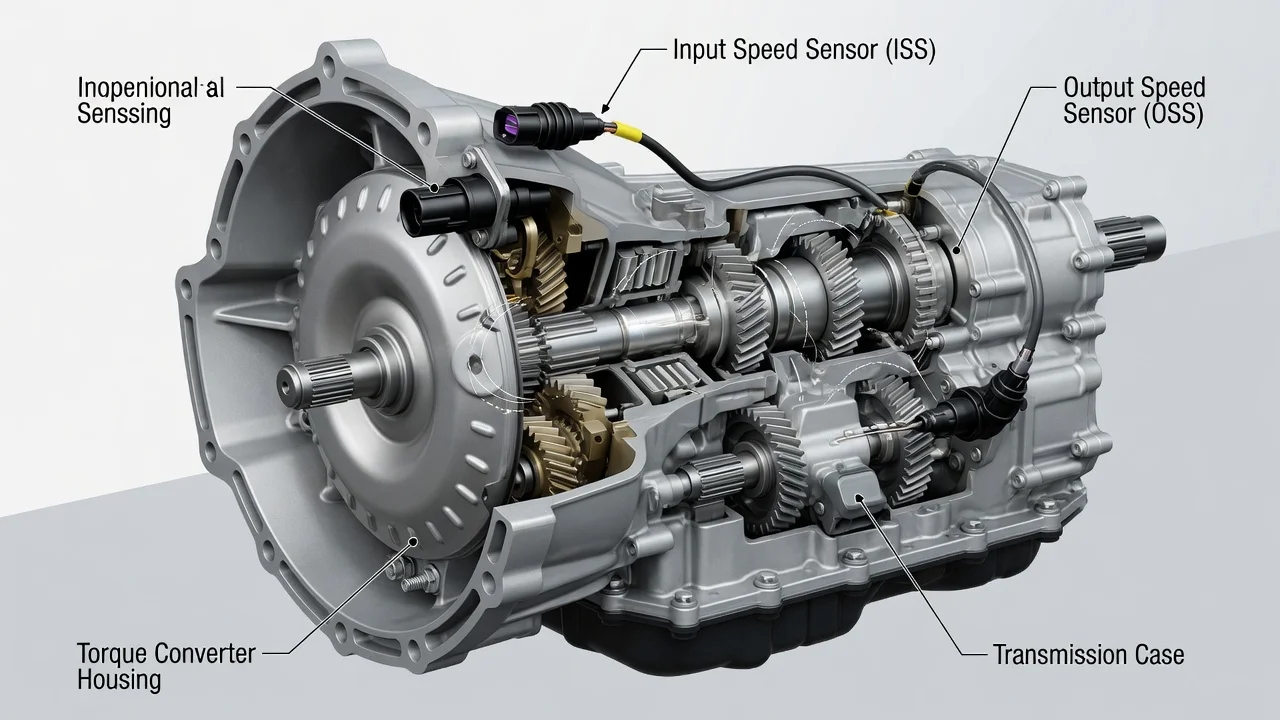
On most Toyota automatics, the transmission speed sensors mount on the outside of the transmission or transaxle case. Each is usually held by a single bolt and connected by a short harness. The exact position depends on the transmission type, drive layout and model year. Identify your unit first, then match the sensor to its circuit. A photo from a different vehicle can point you to the wrong part.
Where Toyota speed sensors are usually mounted
A conventional Toyota automatic typically uses two speed sensors. One is an input or turbine speed sensor, often labeled NT in Toyota terminology. The other is an output speed sensor, often labeled SP2. Many Camry, Corolla, RAV4 and Highlander models use front-wheel-drive transaxles. On these, both sensors usually sit on the transaxle housing, commonly on the top or front face. They are generally reached from the engine bay, sometimes only after removing the air filter box, battery tray or intake ducting. Rear-wheel-drive and four-wheel-drive trucks and SUVs, such as the Tacoma, Tundra and 4Runner, typically carry the sensors on the side of the transmission case. Access there is from underneath the vehicle. Some older models also have a separate vehicle speed sensor on the extension housing or transfer case.
Two important exceptions apply. Many newer Toyotas calculate road speed from the ABS wheel speed sensors rather than a dedicated transmission-mounted vehicle speed sensor. The transmission sensors on these vehicles serve shift control only. Toyota hybrids with a power-split transaxle work differently from a stepped automatic. They do not use the same input and output sensor arrangement, so the usual locations do not apply.
How the sensors work
Each sensor is a magnetic pickup that reads teeth or a reluctor on a rotating part. The input sensor watches a drum or shaft driven by the torque converter turbine. The output sensor reads a gear or rotor tied to the output side of the transmission. The engine or transmission computer compares the two speeds to calculate the current gear ratio and how much slip is occurring. It uses that information to time shifts, control torque converter lockup and adjust line pressure. On some models, the output signal also feeds the speedometer and cruise control.
The computer may set diagnostic codes when a signal drops out or makes no sense, and the check engine light may come on. Often the transmission also enters a fail-safe mode. Typical shift behavior in that mode includes harsh or delayed shifts, staying in one gear, no torque converter lockup or an erratic speedometer. Low fluid, solenoid faults, wiring damage and internal wear can produce the same symptoms. A symptom alone does not confirm a failed sensor.
What changes the location on your vehicle
Transmission type matters most. Stepped automatics with four, five, six or eight speeds each place their sensors differently. CVTs use sensors that read the pulley speeds instead of the classic input and output layout. Manual gearboxes may carry a vehicle speed sensor on the case or rely entirely on the ABS signals. Drive layout changes access too: a front-wheel-drive transaxle, a rear-wheel-drive transmission and a four-wheel-drive unit with a transfer case are worked on from different sides. The same nameplate has also used different transmissions across generations. Within one model year, the four-cylinder and V6 versions may have different units.
Confirm the exact transmission before buying parts or following a video. Many Toyota labels in the driver's door jamb include a transmission or axle code. A VIN decode or a dealer parts lookup by VIN can also confirm it. Treat that code as the reference point for sensor location, fitment and the correct repair procedure.
Finding and checking the sensor yourself
Start with a scan tool rather than a wrench. Generic codes P0715 and P0717 point to the input or turbine speed sensor circuit. P0720 and P0722 relate to the output speed sensor circuit, and P0500 refers to the vehicle speed sensor circuit. Note any freeze frame data, such as vehicle speed and gear when the code set. A scan tool that shows Toyota transmission data lets you compare sensor readings while driving. A code identifies a circuit, not a part. The fault can be the sensor, its connector, the wiring or, less commonly, the control module.
For a visual check, park on level ground, set the parking brake and let the transmission cool. Look for a small sensor with a single bolt and a two-wire connector near the transmission wiring harness. Trace its harness to make sure you have the right sensor. Inspect the connector for oil inside it, corrosion, broken locking tabs and chafed or melted wires. Damaged wiring is a common reason a replaced sensor does not fix the code.
Removing a sensor can let some fluid escape. Many newer Toyota transmissions have no dipstick and require a specific level check procedure at a set fluid temperature. Use the fluid specification listed for your transmission. Many later Toyota automatics use WS fluid, older units commonly used Type T-IV, and CVTs require their own CVT fluid. Order replacement sensors by VIN, because input and output sensors can look alike but are not always interchangeable. Fit a new O-ring, tighten the bolt to the specified torque, clear the codes and road-test. Record the work in the vehicle's service history.
Limitations and next step
This guide describes common patterns, not an exact location for every Toyota. Sensor position and access can differ within a single model line. For a precise location, wiring diagram and test values, use factory repair information for your VIN or ask a Toyota dealer or transmission shop. Avoid long drives in fail-safe mode. Harsh engagements and missing lockup can add heat and wear.
Get a professional diagnosis if the code returns after a sensor replacement or several transmission codes appear together. The same applies if the transmission slips, flares between gears, overheats or has dark, burnt-smelling fluid. These signs suggest a problem beyond the sensor. Repair options then range from a wiring or connector repair to valve body work or a rebuild, and only proper testing can show which one is needed.