Supercharger Bypass Valve Installation and Plumbing
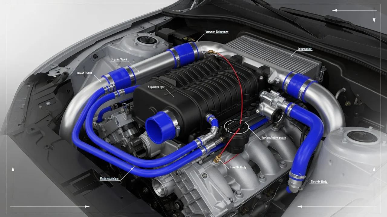
A supercharger bypass valve controls where pressurized air goes when the engine does not need boost. On most systems it routes air from the compressor outlet back to the inlet at idle, light cruise or sudden throttle closure. A failed valve or poorly routed plumbing can cause boost loss, surging, rough idle or drivability faults, so a good installation depends as much on correct hose routing as on bolting in the part. This guide covers confirming the need, preparing, removing, installing and verifying the work.
Confirm the part and repair scope
Bypass valves differ by supercharger design. Positive displacement blowers, such as Roots and twin-screw units, commonly use a butterfly-type bypass valve driven by a vacuum actuator; it stays open under manifold vacuum to cut pumping losses and closes as load rises. Centrifugal superchargers instead use a bypass or blow-off valve near the throttle body that opens when the throttle snaps shut, relieving pressure that would otherwise push back through the compressor and cause surge. Parts for one design are not interchangeable with the other, and even within a design the valve body, actuator, spring and port sizes are matched to a specific kit or factory application. Match the replacement to your exact vehicle configuration, supercharger model and kit revision using the part number on the old unit or the kit documentation.
Before buying anything, make sure the valve is actually at fault. A cracked or disconnected vacuum reference hose, a split coupler or a loose clamp produces the same symptoms as a failed valve: low or erratic boost, a fluttering sound on lift-off, high idle, stalling on deceleration or lean codes. Check the hoses and connections first, then test the valve itself. On actuator-type valves, a hand vacuum pump applied to the actuator should move the linkage smoothly and hold vacuum without bleeding down. On piston or diaphragm valves, look for a torn diaphragm, a sticking piston or a broken spring. Review the service history too; a recently replaced valve that fails again may point to oil contamination from the crankcase ventilation system or an incorrect reference source.
Prepare tools and safe access
Gather the service information for your engine and supercharger before starting: the factory or kit installation manual, the hose routing diagram and any fastener torque values. Typical tools include basic hand tools, a hand vacuum pump, hose picks, a sharp hose cutter, quality clamps of the correct size and boost-rated silicone or reinforced vacuum hose where the kit calls for it. Have new gaskets or O-rings on hand if the valve seals to the intake with one. Work on a cool engine, since supercharger housings, intercooler pipes and the intake manifold stay hot long after shutdown. Disconnect the battery if your service information requires it for nearby sensors or wiring.
Access varies widely. On many centrifugal kits the valve sits in an exposed charge pipe and the job is straightforward. On some factory positive displacement systems, the bypass actuator is mounted on the blower or buried under the intercooler, and reaching it may involve removing the supercharger lid, draining an intercooler coolant circuit or disturbing the blower inlet. That work carries a real risk of debris entering the rotors, coolant leaks and air leaks, and it is better left to a technician if you lack experience with forced induction. The same applies if the change involves a different valve style or spring that would require recalibrating the engine tune.
Remove without avoidable damage
Photograph the area and label every hose before disconnecting anything. A valve has at least two connections that can look similar, and swapping the reference line with an air passage is a common installation mistake. Release clamps fully rather than prying hoses off, because plastic nipples on valves, actuators and intake fittings become brittle with heat and snap easily. Twist a stuck hose to break the seal, or slit it off if it is being replaced anyway.
Unbolt the valve or its flange evenly. On actuator-driven butterfly valves, note the actuator rod position and how it engages the valve shaft lever, and avoid bending the bracket or rod, which changes the preload and opening point. As soon as the valve is out, cover open ports in the supercharger, charge pipe or intake with clean tape or caps. A dropped bolt, a piece of old gasket or a chunk of broken plastic that reaches the rotors or compressor wheel can cause serious damage. Clean mating surfaces with the openings covered and wipe them down before installing the new part.
Install and restore the system
Install the valve in the correct direction. Most units are marked with a flow arrow or labeled ports: the inlet side connects to the pressurized side of the system, and the outlet returns air to the low-pressure side ahead of the compressor. Fit new seals, start fasteners by hand and tighten them to the values in your service information rather than guessing, since overtightening can crack plastic and aluminum housings. On actuator-type valves, reconnect the linkage at its original position unless the instructions specify an adjustment.
Plumbing determines whether the valve works properly. The control or reference line normally connects to a manifold vacuum source below the throttle plate, so the valve sees vacuum at idle and deceleration and boost under load; a ported or atmospheric source will keep it from responding correctly. On engines with a mass airflow sensor, the valve should recirculate into the intake tract after the sensor rather than vent to the atmosphere, unless the kit and tune are designed for venting. Dumping metered air can cause rich running, hesitation or stalling on lift-off. Keep hoses as short and direct as practical, avoid sharp bends that kink, route lines away from exhaust heat, belts and pulleys, and use the right clamp on every joint.
Some valves have adjustable spring preload or interchangeable springs; set these only as the kit instructions direct for your boost level and operating conditions. Reconnect the battery and any sensors that were unplugged. Depending on the vehicle, the engine control module may need to relearn idle after battery disconnection, so follow the procedure in the service information if one is specified.
Check the completed work
Before starting the engine, recheck every clamp and compare hose routing against your photos and diagram. A smoke test or a pressure test of the intake tract, using suitable fittings and the test pressure given in your service information, is the most reliable way to find leaks in new plumbing. With the engine running, listen for hissing and confirm that idle speed settles normally. On actuator valves you can watch the linkage: on most designs it sits open at idle and moves toward closed as load increases.
On a road test, check for smooth throttle response, no surge flutter on lift-off and no stalling when coming to a stop. If you have a boost gauge, compare readings with what the kit or manufacturer specifications indicate for your setup, and use a scan tool to review fuel trims and stored codes. Further diagnosis is needed if boost stays lower than expected, idle hunts, the engine stalls on deceleration, lean or airflow codes appear, or the valve shows oil. Recheck clamps and hoses after the first few heat cycles, since new hose can relax, and add the valve and its lines to routine inspection in your maintenance schedule.