Prodigy P2 Trailer Brake Controller Manual: Setup, Adjustment and Troubleshooting Guide
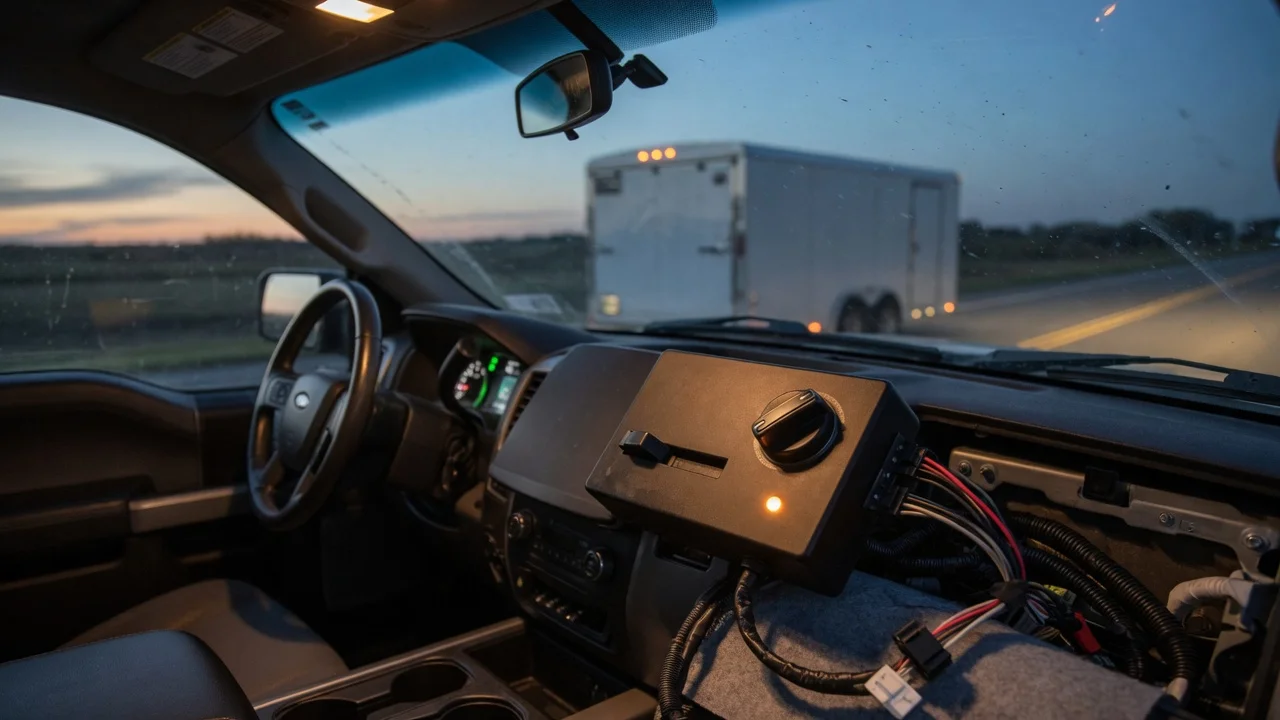
What the Prodigy P2 Manual Covers
The Prodigy P2 is a proportional inertia-based trailer brake controller designed for light- to medium-duty towing. Its manual explains how the controller detects tow vehicle deceleration and applies trailer brakes in proportion to that motion. The guide covers mounting orientation, electrical connection, initial power-up, setting the maximum output level, manual override use, and reading the diagnostic display. The instructions apply to the standard P2 control unit; wiring harness adapters and vehicle-specific connectors are sold separately and vary by tow vehicle make and model.
Mounting and Orientation Requirements
The P2 must be mounted with the manual lever and display facing the driver, and the unit must be secured so it cannot move independently of the tow vehicle. The controller needs to be installed in a position where it sits level from side to side and is aligned with the direction of travel. It should not be mounted in a location that exposes it to direct high heat, water spray, or areas where the driver cannot reach the manual control comfortably. The mounting bracket must be attached to a rigid surface; a loose or flexing mount can affect the accelerometer and cause inconsistent trailer braking.
Electrical Connection and Vehicle Wiring
The P2 uses a four-wire connection: 12-volt power, ground, brake signal input, and trailer brake output. The manual directs users to connect the black wire to a fused 12-volt supply, the white wire to chassis ground, the red wire to the tow vehicle’s brake switch cold side, and the blue wire to the trailer brake circuit at the trailer connector. The 12-volt supply should be protected with an appropriate circuit breaker or fuse according to the installation instructions. Wiring gauge, routing, and the use of a dedicated power feed are important for stable operation and to avoid voltage drop under load.
Initial Power-Up and Display Behavior
When the P2 is first connected and the tow vehicle ignition is on, the controller runs an internal check and the digital display illuminates. Without a trailer connected, the display typically shows a single dot or a steady indicator to confirm standby mode. If the display flashes or shows a diagnostic code immediately after power-up, the manual directs the user to verify the wiring connections and trailer brake circuit. The device does not need to be taught the vehicle’s braking curve; it continuously measures deceleration while driving.
Setting the Power Level
The P2 uses a power setting that controls the maximum braking force sent to the trailer when the tow vehicle is stopping hard. The manual explains that the power level should start low and be increased gradually during a controlled test stop on a dry, straight, low-traffic road. The goal is to have the trailer brake firmly without locking its wheels and without the trailer pushing or pulling the tow vehicle. The display shows the current power level during adjustment. The correct setting varies with trailer weight, load, brake condition, and road surface, so it should be checked whenever the load changes significantly.
Manual Override Function
The manual control lever on the front of the P2 allows the driver to apply the trailer brakes without using the tow vehicle brake pedal. Squeezing the lever gradually increases trailer braking up to the set power level. The manual describes this as a way to correct trailer sway or check trailer brake function at low speed. Releasing the lever releases the trailer brakes. The override does not change the stored power setting, and it works even when the tow vehicle brake pedal is not pressed.
Reading Diagnostic Codes and Warnings
The P2 display uses flashing patterns and numeric or letter codes to report connection and output problems. The manual lists the codes and their meanings. An open circuit on the trailer brake output, a short circuit to ground, a short to battery voltage, or a loss of trailer connection will trigger a specific display message. When a code appears, the controller may reduce or stop trailer braking output to protect the unit and wiring. The user should correct the wiring or connection fault, then cycle the ignition or reconnect the trailer to clear the active fault.
Common Troubleshooting Steps
Check the trailer connector and brake magnet wiring for corrosion, loose terminals, or broken insulation. Confirm the P2 ground connection is clean, tight, and directly attached to vehicle metal. Verify the brake switch signal reaches the red wire when the brake pedal is pressed. Test the trailer brake circuit with the manual override at low speed; a complete lack of response suggests an output or wiring fault. If the display shows no power, check the fuse or circuit breaker on the P2 power feed. If trailer brakes lock during light braking, reduce the power level and retest.
Calibration and Driving Behavior
The P2 does not require a manual calibration sequence after installation, but the manual notes that the controller learns the tow vehicle’s deceleration behavior during normal driving. It applies trailer braking in proportion to the sensed deceleration and the set power level. At very low speeds, proportional output may be minimal; the manual override can be used to confirm trailer brake operation. If braking feel changes after loading, unloading, or adjusting the hitch, the power setting should be reviewed.
Limits and Model Variants
The instructions in the P2 manual apply to the non-integrated aftermarket controller. Factory trailer brake controllers integrated into a tow vehicle use different menus, displays, and diagnostic procedures. Some P2 units may have slight display differences depending on production version, but the core operation and wiring remain consistent. The manual does not supply maximum towing or trailer weight ratings; those limits come from the tow vehicle manufacturer and trailer specifications.
Next Step for the Owner
Use the manual’s basic setup sequence first: secure the controller, connect the four wires, power the unit, set a low initial power level, then perform controlled stops while raising the level until trailer braking is firm and balanced. If a diagnostic code appears during setup or towing, address the specific wiring or output fault before continuing. Keep the manual accessible in the tow vehicle so the code table and adjustment steps are available during a trip.