Planning an EV Charging Station Layout
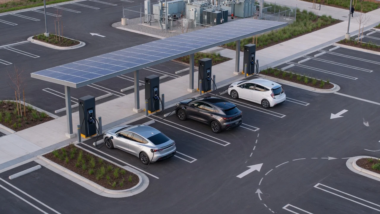
An EV charging station layout is the physical arrangement of parking stalls, chargers, cables, drive aisles, pedestrian paths, and electrical equipment so vehicles can enter, park, connect, charge, and leave in a predictable way. The layout also has to keep power equipment reachable for service and keep people clear of live hardware. The right arrangement depends on who uses the site, how long they stay, which vehicles and connectors are expected, and how much electrical capacity the property can supply.
What the layout has to accomplish
A workable layout does four jobs at once. It matches stall count and charger power to dwell time, so a workplace all-day park and a highway stop do not share the same stall pattern. It places each dispenser where a typical vehicle’s charge port can reach the connector without blocking the next stall. It keeps inbound, charging, and outbound traffic from crossing in tight space. And it leaves room for transformers, switchgear, meters, and future chargers so the first installation does not freeze the site.
Those jobs change with the use case. A single-family driveway is usually one or two Level 2 wall units on a dedicated circuit, with cable reach and garage or curb clearance as the main constraints. A multifamily or workplace lot adds shared stalls, wayfinding, access control, and after-hours parking rules. A public or retail site adds short-stay turnover, payment hardware, lighting, and visibility from the aisle. A fleet depot or depot-style yard often uses assigned stalls, higher power, overnight sequencing, and pull-through or head-in rows sized to the vehicles in service. A highway or corridor DC fast site is built around short dwell, high power, pull-through stalls, and clear separation of waiting, charging, and exit lanes.
Charger type sets stall time and spacing
AC Level 1 charging uses a standard household-type 120-volt circuit in markets where that service is common. Power is low, so a full charge can take many hours. It is mainly a home or workplace overflow option and rarely drives a public-station layout.
AC Level 2 charging is the usual choice for homes, workplaces, multifamily properties, and destination parking. In North America it is commonly associated with 208- or 240-volt service and onboard-charger limited power, often in a range of about 6 kW to 19 kW per vehicle depending on the charger, the vehicle, and the circuit. Exact output is equipment- and vehicle-specific. Stalls can be perpendicular, angled, or parallel. Cable management matters because ports sit on different corners and sides by model and market.
DC fast charging supplies high-voltage direct current to the battery and is used where dwell is short: corridors, retail, fleet turnaround, and some public hubs. Published charger ratings commonly run from about 50 kW to 350 kW or higher per dispenser, with the vehicle’s battery system setting the actual session rate. Fast-charge stalls need more electrical equipment nearby, more heat and noise clearance around cabinets, and often pull-through geometry so a vehicle does not have to reverse into circulating traffic with a cable attached.
Connector family is a layout input, not a footnote. North American AC charging has long used the SAE J1772 coupler; DC charging has used Combined Charging System (CCS) Combo 1, CHAdeMO on some older and imported models, and, on a growing share of new vehicles, the North American Charging Standard documented as SAE J3400. Adapter use, dual-cable dispensers, and pull-up direction all follow from which ports the site intends to serve. Markets outside North America use different AC and DC coupler families, so a layout copied from another region can place the dispenser on the wrong side of the stall.
Stall geometry and vehicle approach
Start with the vehicle mix: passenger cars, crossovers, light trucks, vans, and medium-duty fleet units do not share the same length, width, turning radius, or port height. A stall that fits a compact car can leave a pickup’s port short of the cable or push a van into the drive aisle. Where the site will see mixed traffic, size the charging stalls to the largest regular user and treat smaller cars as able to use the extra room.
Port location varies by automaker, model year, and body style. Common positions include front fender, front corner, rear quarter, and, on some vehicles, the front fascia. Because of that spread, a dispenser at the front-left corner of a stall will serve some vehicles easily and leave others needing a long cable or a second pull-in. Practical responses include centering a dual-port pedestal between two stalls, providing cables long enough for typical port reach while keeping unused cable off the ground, marking pull-in direction, and, on DC sites, using pull-through islands so the driver can choose which side faces the dispenser.
Standard parking-stall width and length come from local zoning, the property’s existing lot striping, and accessibility rules. Charging stalls often need extra width or a shared access aisle for door opening, wheelchair boarding, and cable handling. Exact stall dimensions, access-aisle widths, slope limits, and the number of accessible charging spaces are set by the authority having jurisdiction and by the accessibility standard that authority enforces. Those numbers are not universal; they should be taken from the applicable code set for the site rather than from a generic template.
Drive-aisle width, turning radius, and whether stalls are head-in, back-in, angled, or pull-through control both safety and utilization. Head-in stalls use less land and suit longer dwell. Pull-through islands suit DC fast charging and vehicles that tows a trailer or that the driver prefers not to reverse. Angled stalls can ease entry in one-way aisles and complicate exit if the charger and cable sit on the tight side. Wheel stops, bollards, and curb islands protect dispensers from low-speed contact; they also have to leave enough room for the charge port, an open door, and a person standing with a connector in hand.
Electrical equipment, utilities, and future capacity
The parking layout and the electrical layout are one design. Dispensers are only the visible end of a chain that can include a utility service upgrade, transformer, switchboard or panelboard, meters, disconnects, and, on DC sites, power cabinets that may sit several meters from the dispenser. Cabinet location is constrained by manufacturer working clearances, ventilation, flood elevation, vehicle impact protection, and the maximum cable or DC feeder length the equipment allows. Putting all of that gear in the cheapest leftover corner can force long, costly feeders or leave no path for a service vehicle.
Available service capacity often caps stall count and power before parking geometry does. A row of Level 2 chargers on a workplace lot may share a panel with load management that lowers per-stall power when many vehicles plug in at once. A small number of high-power DC stalls can require a new transformer and a utility lead time measured in months. Until a load study and a utility response exist, stall counts in a concept plan are placeholders.
Conduit, pull boxes, and spare electrical capacity are layout decisions. Running raceways under stalls, islands, and future parking rows during the first pour is usually cheaper than cutting pavement later. A measured approach is to install the number of powered stalls the load will support now, and to place empty conduit, pad space, and striped stalls for a documented second phase. Nameplate current, voltage, and simultaneous-use assumptions belong on the electrical drawings; they should match the charger submittals rather than a generic kilowatt figure.
People, weather, and day-to-day use
Pedestrian paths should reach the charger without crossing an active drive aisle if the site can avoid that crossing. Lighting, sight lines, and camera coverage belong in the same plan as stall striping because a charging session often happens after dark and can last longer than a fuel stop. Payment pedestals, instruction placards, and unit numbers need to be readable from the driver’s seat and from the charger face.
Cable handling is a daily operations issue. Retractors, holsters, and defined drape points keep connectors off the pavement, reduce trip hazards, and limit damage from being run over. Outdoor equipment ratings, enclosure type, and cold-weather cable flexibility are specified by the charger maker and by the electrical code in force; layouts in freeze-thaw or coastal climates also need drainage away from pads and bases.
Accessible charging is part of the core layout, not an add-on stall at the edge of the lot. An accessible charging space has to let a person using a mobility device approach the vehicle, reach the connector, operate the user interface, and depart, with a surface slope and reach range that meet the accessibility standard the site must follow. Van-accessible geometry, shared access aisles, and dispenser height and side reach are typical controls. The required count of accessible charging spaces is jurisdiction-specific.
A practical planning sequence
Define the use case: home, multifamily, workplace, public destination, fleet, or corridor fast charging, including typical dwell time and whether stalls are reserved or first-come. List the vehicles and connectors the site must serve now, and the models reasonably expected within the first expansion phase. Measure existing stall size, aisle width, grades, lighting, drainage, and the path from the electrical service to the proposed islands. Obtain a load study and a utility or building-service constraint before locking stall count or DC power level. Place stalls and dispensers around port reach, accessible spaces, and traffic flow; then place cabinets, transformers, and protection around those stalls. Protect equipment with bollards or islands, keep manufacturer and code clearances, and route pedestrians away from backing vehicles. Plan conduit, spare capacity, and striped future stalls so a second phase does not rebuild the first. Have the layout reviewed against the electrical code, building code, zoning, and accessibility rules that apply at the address, because those rules control dimensions and equipment placement.
What remains site-specific
No single stall diagram fits every property. Charger output, connector type, and onboard-charger limits vary by model year, trim, and market. Stall width, accessible-space counts, working clearances, and setbacks are code- and jurisdiction-dependent. Utility capacity, transformer lead time, and whether load sharing is allowed are decided with the utility and the electrical designer. Flood elevation, snow storage, and fire-access lanes can move an island after the parking sketch looks finished.
A sound next step is a scaled site sketch that shows vehicle paths, stall types, dispenser locations, cabinet pads, and the electrical service route, paired with charger cut sheets and a load summary. That package is what a civil or electrical designer and the local reviewer can turn into dimensions that are legal and buildable for the specific lot.