P2626–P2631 Oxygen Sensor Pumping Current Trim Circuit Codes
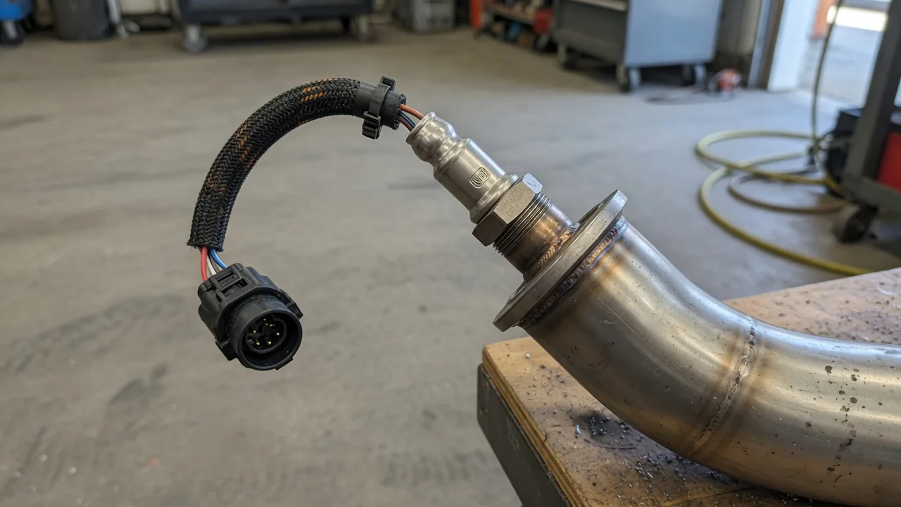
P2626, P2627, P2628, P2629, P2630, and P2631 codes report a monitored problem in the pumping current trim circuit of a wideband oxygen sensor, also called an air-fuel ratio sensor, at bank 1 sensor 1 or bank 2 sensor 1. Open, low, and high circuit conditions describe electrical findings, not a confirmed failed sensor. Exact meaning and test steps depend on the vehicle's year, make, model, and engine.
Confirm the Code Definition and Sensor Location
Before interpreting a P2626 code or any related pumping current trim circuit code, match the stored description and the manufacturer diagnostic procedure to the vehicle's year, make, model, and engine. Wideband air-fuel ratio sensors do not all use the same internal layout. In many designs, pumping current moves oxygen ions so the sensor can report a broad air-fuel range, and a trim circuit lets the control module adjust that current. The published circuit names and pinouts still have to come from that vehicle's service information.
Bank 1 contains the cylinder numbered one, and sensor 1 generally identifies the upstream wideband oxygen sensor. Bank 2 is the opposite bank on a V-type or similar engine, and its physical side of the vehicle is not the same on every layout. A circuit code flags a monitored electrical condition such as an open circuit, circuit low, or circuit high. That finding is evidence to interpret; it does not by itself prove the sensor needs replacement.
P2626 and P2629: Pumping Current Trim Circuit Open
A P2626 code typically points to an open pumping current trim circuit at bank 1 sensor 1, while a P2629 code typically points to the same type of open circuit at bank 2 sensor 1. Those standard descriptions still need vehicle-specific confirmation because manufacturers can assign slightly different wording. Electrically, an open circuit means the monitored path is interrupted so expected current cannot complete the loop. It does not describe a hole in the exhaust or an unsealed exhaust joint.
The interruption can sit inside the air-fuel ratio sensor, in a disconnected or damaged sensor wiring harness, or at connector terminals that no longer make solid contact. None of those locations can be ranked as most likely without the correct diagram and inspection. Intermittent contact may set P2626 or P2629 only under certain temperatures, vibration, or load. Freeze-frame data captures those conditions, and professional circuit testing is needed to catch a break that is not present at every key cycle.
P2627 and P2630: Pumping Current Trim Circuit Low
A P2627 code is the usual label for pumping current trim circuit low at bank 1 sensor 1, and a P2630 code is the usual counterpart at bank 2 sensor 1. Low refers to the electrical condition the control module detected under that manufacturer's criteria. It does not establish that the engine is running a lean mixture, and it should not be read as a fuel-trim diagnosis by itself. Vehicle-specific confirmation is still required before acting on either code.
Possible contributors include a short in the sensor wiring harness, an internal fault in the wideband oxygen sensor, or a supply or control problem on the pumping current trim circuit. Which of those applies depends on the schematic for that engine. A reading is abnormal only when it falls outside the manufacturer test limits under the specified operating conditions. Comparing a live value to a generic range, or replacing the sensor because the P2627 code or P2630 is stored, skips that required comparison.
P2628 and P2631: Pumping Current Trim Circuit High
A P2628 code typically indicates pumping current trim circuit high at bank 1 sensor 1, and a P2631 code typically indicates the same high-circuit condition at bank 2 sensor 1. High describes the monitored electrical state, not a proven rich mixture. Fuel-system richness is a separate question that requires mixture, fuel-trim, and related data. Manufacturer-dependent definitions can still differ in how the high threshold is detected. Confirm each P2628 code or P2631 code against that vehicle's service text.
Depending on that circuit design, a short to voltage, an internal sensor problem, or a connection fault at the connector terminals can produce a high reading. Those possibilities are starting points, not a ranked cause list. A high-circuit code alone cannot identify a failed control module, because the module is only one of several devices on the path. Replacing a module on the strength of P2628 or a P2631 code, without isolating wiring and the air-fuel ratio sensor, is not justified by the code itself.
Symptoms and When to Stop Driving
A pumping current trim circuit fault may illuminate the malfunction indicator light, and some vehicles also show rough running, hesitation, or increased fuel consumption. Noticeable drivability symptoms can also be absent while the code is stored, so a quiet engine does not rule out P2626, P2629, or the related low and high circuit codes. Symptoms also cannot reliably identify whether bank 1 sensor 1 or bank 2 sensor 1 is involved, or whether the underlying problem is an open circuit versus circuit low or circuit high.
Stop driving as soon as it is safe and arrange assistance if the malfunction indicator light flashes, if there is a severe misfire, stalling, or a substantial loss of power. Those conditions can damage the catalytic converter or leave the vehicle difficult to control. When the warning light is steady and the vehicle otherwise operates normally, follow the owner's manual and arrange prompt diagnosis rather than ignoring the light. An unresolved wideband oxygen sensor circuit fault can still allow mixture control to drift.
Safe Observations Before a Diagnostic Appointment
Before a shop visit, record every stored and pending code, including related trim-circuit codes if more than one is present, plus available freeze-frame data. Note whether the fault followed recent exhaust, engine, or wiring work, because a disturbed sensor wiring harness or connector terminals can set a trim-circuit code after that service. Clearing codes before that record is made removes useful diagnostic context, including the operating snapshot that shows when the pumping current trim circuit first failed the monitor.
With the engine off and the exhaust fully cool, an owner can look at readily visible wiring and connectors for obvious damage, burned insulation, or loose routing. Do not disturb components, unplug the air-fuel ratio sensor, or force a connector that is not already loose. Wire piercing, jumper tests, applied voltage, work on a hot exhaust, and access beneath an unsupported vehicle are not owner tasks. Those steps can injure people, damage circuits, and confuse later professional testing of an open circuit, circuit low, or circuit high condition.
Professional Testing and Repair Verification
A technician starts with the correct wiring diagram, connector identification, and the manufacturer diagnostic sequence, then reviews related codes so a pumping current trim circuit finding is not isolated from heater, signal, or other air-fuel sensor faults. Circuit integrity, terminal condition, and scan data need sensor-specific procedures and suitable equipment. Generic voltage or resistance targets are not a substitute, because wideband oxygen sensor pumping current circuits are not built to one shared electrical standard across every engine family.
Testing should establish whether the sensor wiring harness, connector terminals, the wideband oxygen sensor itself, or a control circuit needs repair before parts are ordered. After a repair, verification means running the manufacturer-specified operating conditions, checking whether the stored code returns, and confirming monitor results where the scan tool reports them. Clearing the malfunction indicator light alone does not confirm that an open circuit, circuit low, or circuit high condition has been corrected.