P2579 and P2580: Turbocharger Speed Sensor Circuit Codes
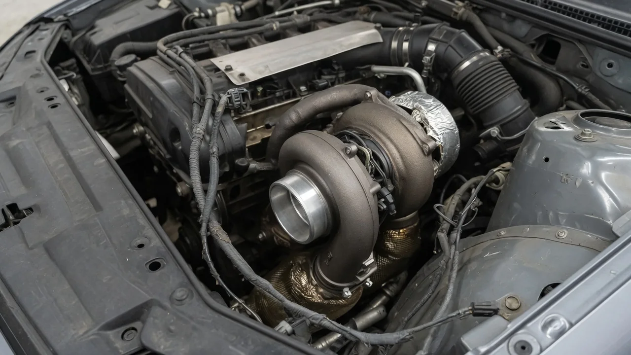
Diagnostic trouble codes P2579 and P2580 point to the turbocharger speed sensor circuit, but their exact meanings depend on the vehicle manufacturer’s monitoring strategy. P2579 often indicates a range or performance fault, while P2580 suggests a low circuit input. These codes signal that the powertrain control module has detected a signal outside expected parameters, not necessarily a failed turbocharger. Understanding the difference guides proper inspection and prevents unnecessary parts replacement.
Verify the Vehicle-Specific Meaning of P2579
Before interpreting P2579, confirm the definition for the exact year, make, model, and engine using service information. Some vehicles use manufacturer-specific code assignments that differ from generic OBD-II descriptions. Where P2579 is verified as a turbocharger speed sensor range/performance fault, the control module has received a signal that fails plausibility checks—such as an unrealistic frequency, duty cycle, or sudden change inconsistent with engine load and boost demand.
A range/performance code does not automatically condemn the sensor or the turbocharger. The signal could be distorted by a poor ground, electromagnetic interference, or mechanical wear in the sensor’s target wheel. The control module compares the speed signal against expected values from other sensors, and many conditions can create a mismatch. Therefore, diagnosis requires foundational tests of the sensor circuit and turbo shaft integrity before any part is replaced.
Verify the Vehicle-Specific Meaning of P2580
Similarly, P2580 requires verification against the vehicle’s factory diagnostic information because not all manufacturers assign the same low-circuit code to the turbo speed sensor. When confirmed, a low circuit input means the module detected a voltage or frequency below the calibrated threshold under the specified monitoring conditions. This could occur only at certain engine speeds or temperatures, captured as a pending or matured fault.
A low signal from the turbocharger speed sensor circuit does not prove that the shaft is turning slowly or that boost is low. The sensor may be unplugged, a wire may be chafed and grounded, or the sensor may have lost its supply voltage. Even a perfectly healthy turbocharger can set this code if the electrical reporting path fails. Replacing the turbocharger based on this code alone would ignore the electrical causes that are far more common.
Symptoms and Signs That Require Stopping
Some drivers notice a check engine light or a limp-mode condition with reduced engine power, while others experience no change in drivability. The vehicle may limit boost to protect the engine when the speed signal is unreliable, causing sluggish acceleration or unexpected surge. These protective strategies vary by manufacturer and calibration. Symptoms reflect the module’s response to missing data, not necessarily the physical state of the turbocharger.
Severe symptoms warrant immediate caution. Heavy smoke from the exhaust, loud metallic noise from the turbo area, loss of oil pressure, or an overheating warning could indicate mechanical failure beyond an electrical signal issue. Continuing to drive under those conditions may cause engine damage. Pull over when safe, shut the engine off, and arrange professional assistance rather than attempting to continue the journey.
Record Scan Data Before Clearing Codes
Before clearing any diagnostic trouble codes, use a scan tool to record all stored and pending codes along with available freeze-frame data. This snapshot includes engine speed, load, coolant temperature, and vehicle speed at the moment the fault was detected. Such context reveals whether the signal problem appears at idle, during acceleration, or at steady cruise. Save or photograph the information because clearing erases this valuable evidence.
Note when the warning light first appeared and any recent repairs, especially turbocharger, exhaust, or electrical work. Avoid intentionally recreating hard acceleration or high-load driving simply to make the code return. A cleared code may stay away for many drive cycles even if the fault is still intermittent. Related codes, such as boost control or circuit codes for other sensors, help the technician determine whether the problem is isolated or part of a shared harness fault.
Safe Observations and Plausible Fault Sources
With the engine off and fully cool, you can safely look for visible problems around the turbocharger and its wiring. Check for insulation rubbed through by heat shields, connectors that are not fully seated, or harness sections pinched against brackets. A displaced wire that touches the exhaust manifold or turbo housing can melt and short the signal to ground, producing a low circuit code. Do not reach near hot or moving parts.
The possible fault sources include the speed sensor itself, its connector terminals, the wiring between the sensor and the control module, and applicable power or ground feeds. A range/performance fault may also appear if the sensor gap to the target wheel is wrong or if the wheel is damaged. Without testing, none of these can be assumed. Report any visible damage to a professional, but leave electrical probing and component replacement to trained hands.
Professional Testing and Repair Confirmation
A technician begins with the verified wiring diagram and the manufacturer’s pinpoint test for P2579 or P2580. The procedure systematically checks sensor supply voltage, ground integrity, and the signal line for opens, shorts, or high resistance. It also specifies the expected frequency or voltage from the sensor under defined conditions. Because the sensor often produces a digital square wave, an oscilloscope or high-end scan tool may be needed to view the signal pattern rather than just a static reading.
A replacement recommendation for the sensor, wiring repair, or turbocharger should be made only after this testing identifies the failed component. A control module should be suspected last, after all external circuits pass. After the repair, the technician clears codes, performs the prescribed drive cycle, and confirms that the fault monitor runs and passes. Symptom improvement and a completed monitor are necessary; an extinguished warning light alone does not prove the repair was effective.