P2552 Code: Throttle/Fuel Inhibit Circuit Meaning, Causes and Diagnosis
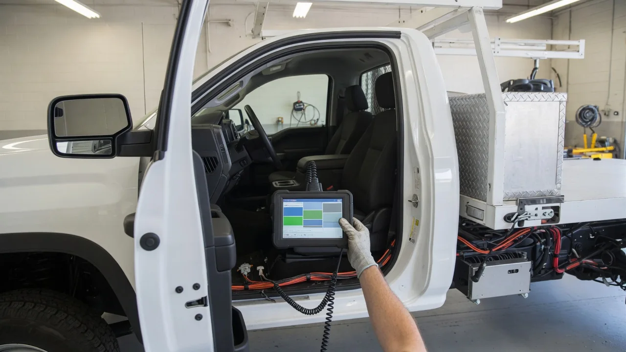
A P2552 code signals a possible fault in the throttle/fuel inhibit circuit, a system often used on work trucks, PTO-equipped vehicles and fleet upfits to limit engine output under specific conditions. Drivers may see reduced engine power or abnormal throttle response, though symptoms vary. Understanding the vehicle-specific definition is essential, because the same code can point to different circuits depending on the manufacturer.
What P2552 Means and Why You Must Check the Vehicle-Specific Definition
P2552 is generally described as a throttle/fuel inhibit circuit fault, and some sources add 'range/performance' to that description. The inhibit circuit lets an external signal, such as a switch or upfitter interface, tell the engine control module to limit or block throttle or fuel demand under certain conditions. A stored code means the module detected an electrical or signal problem in that circuit, not that a specific part has definitely failed. The exact enabling conditions and monitored circuit depend on the manufacturer.
Because the code definition varies, readers must check the factory service information for their make, model, year and engine. In some vehicles this circuit is linked to PTO operation or auxiliary equipment interlocks; in others it may relate to a safety interlock. Without the vehicle-specific definition, you could misdiagnose a simple connector issue as a failed module. Always confirm the range/performance criteria and expected signal values before interpreting live data or freeze frame data.
Why P2552 Often Shows Up on PTO-Equipped and Fleet Upfit Vehicles
Power take-off (PTO) systems on work trucks and fleet vehicles often use inhibit or interlock inputs to control engine speed or throttle response while stationary. For example, when a PTO is engaged, the engine control module may limit maximum throttle opening to protect driven equipment. Aftermarket or body-builder wiring connected to upfitter interface circuits can affect the signal the module expects. A loose or improperly terminated wire can create a voltage reading that falls outside the normal range and sets P2552.
Recent equipment installs, removals or modifications are worth recording as context when P2552 appears. A new auxiliary hydraulic pump or lighting system tapped into an upfitter circuit could alter the electrical load or introduce a poor connection. However, avoid assuming the new equipment caused the fault. Many P2552 codes occur on entirely stock vehicles due to corrosion or wire chafing. Service information for the specific vehicle should be used to identify the exact inhibit input and its expected behavior.
Symptoms Drivers May Notice With a P2552 Code
Drivers may notice a check engine light, limited throttle response, reduced power, or PTO/auxiliary functions that don't work as expected. Some vehicles may show no noticeable drivability change, because the manufacturer may only use this circuit under rare conditions, such as engaging an auxiliary output. Symptoms depend on how the manufacturer uses the circuit and whether the fault is active during normal driving. When a fault is present, the module may default to a safe reduced power mode.
Note when symptoms happen: at startup, while stationary with equipment running, or while driving at highway speeds. If the engine loses power or throttle response becomes unpredictable in traffic, that can be a safety concern. The same is true during equipment operation if a PTO-driven device suddenly stops or changes speed. Even without obvious symptoms, a stored P2552 should be checked promptly to avoid compounding failures in the wiring harness or module.
Possible Causes Behind a Throttle/Fuel Inhibit Circuit Fault
Possible causes fall into several general categories: damaged or chafed wiring, corroded or loose connectors, faulty switches or inputs on upfit equipment, and issues in the controlling module or its software. A rubbed harness near a frame rail or a connector packed with road salt can create high resistance that the module reads as an open or short circuit. Aftermarket accessories tapped into vehicle circuits can create unexpected signal conditions, such as voltage backfeed or intermittent ground faults.
Low system voltage or other stored codes may affect how the module reads the circuit. A weak battery or failing alternator can shift the reference voltage enough to trigger a range/performance fault. Technicians should never assume a single cause without testing based on the vehicle's wiring diagram. Pinpointing the fault often requires measuring voltage, resistance and continuity at the module and the inhibit switch, then comparing those values to the manufacturer's specifications.
Safe Checks You Can Do Before Visiting a Shop
Before visiting a shop, record freeze-frame data and any other stored codes with a scan tool; do not clear anything until that data is saved. Freeze frame captures the engine temperature, rpm, vehicle speed and other conditions when the fault set, which helps a technician reproduce the problem. Visual checks that don't require disassembly are safe: look for obvious loose connectors near upfit equipment, visible wire damage along the frame or body, or recently added accessories that may have pierced a harness.
Clearing the code and watching whether it returns can be informative, but it does not fix the problem. If the code resets quickly, the fault is likely active; if it stays away for days, an intermittent issue may be present. Avoid probing, splicing or backprobing module circuits without the correct wiring diagram and experience. A slipped probe can short a 5-volt reference to battery voltage and damage the engine control module, turning a simple connector repair into an expensive module replacement.
How Professional Diagnosis of P2552 Usually Works
Professional diagnosis starts from manufacturer-specific code definitions, diagnostic flowcharts and wiring diagrams for the exact vehicle. Technicians use a scan tool to view the inhibit input state in live data, then follow the published test steps. Circuit testing checks signal integrity, continuity and module input behavior, often using a digital multimeter and an oscilloscope. The goal is to determine whether the fault is in the wiring, a switch, a connector or the module itself.
Checking for applicable technical service bulletins or software updates may be part of the process, though readers should not assume one exists. If aftermarket PTO or fleet equipment is connected to the circuit, involving the upfitter or body builder can save time. They may know exactly which wire was tapped and whether a diode or relay was added. Without that information, a technician might spend hours tracing an unfamiliar circuit that the factory diagram does not show.
Is It Safe to Drive With P2552 and What to Expect Next
Driveability and risk depend on how the vehicle responds. Unexpected power limits or throttle behavior call for caution and prompt inspection. If the engine occasionally falls into reduced power on a busy road, that creates a hazard. Avoid relying on PTO or work equipment functions until the fault is understood. Operating a hydraulic lift or aerial device when the inhibit circuit is unstable could cause sudden movement or load loss.
Repair scope and cost vary widely by the cause found; a simple connector cleaning may resolve it, while a module failure could be costlier. The key takeaway is to verify the vehicle-specific meaning, record the data, do only safe visual checks, and get professional circuit testing. P2552 is a diagnostic starting point, not a parts replacement order. With the right service information and methodical testing, most faults in this circuit are repairable without guesswork.