P2505, P2507, P2509 and P2510: ECM/PCM Power Input and Relay Codes
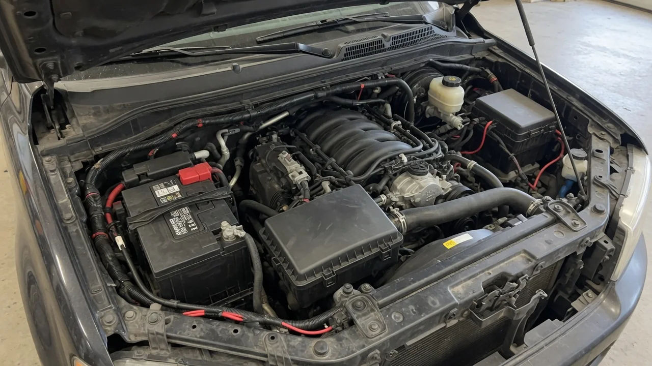
When a scan tool reports P2505, P2507, P2509, P2510, or P2511, the engine control module is flagging a problem with how it is powered or how it monitors that power path. These codes describe a monitored condition, not a failed computer by themselves. Confirm each definition against the vehicle's year, make, model, and engine, then inspect supply, ground, and relay-sense circuits before replacing parts.
Verify P2505 and P2507 Definitions for the Vehicle
A P2505 code is commonly described as an ECM/PCM power input signal concern, and a P2507 code is commonly described as that same power input signal reading low, but those labels are not interchangeable across every manufacturer. Before treating either result as a diagnosis, compare the stored wording and the enable criteria in the service information for that year, make, model, and engine. The module is reporting what its monitor saw, not a universal circuit definition, so the same numeric identifier can describe different thresholds or pin assignments on different platforms.
An interrupted supply can come from an open path or from resistance high enough to starve the module under load, yet that does not make P2505 a blanket open-circuit verdict. Voltage can sag at the module while still appearing present at a battery post, especially if a terminal, splice, or connector is compromised. A stored code documents a monitored condition that met the controller's criteria; it does not establish that the ECM or PCM has failed internally or that replacement is required. Confirm power integrity first, because a healthy module cannot operate correctly on a weak feed.
What P2509 Can Reveal About Intermittent Module Power
After the vehicle-specific definition is confirmed, a P2509 code typically points to an intermittent ECM/PCM power input signal rather than a constantly missing feed. That distinction matters because the interruption may last only long enough to reset the controller or to store a fault, then recover before a technician arrives. Some drivers notice difficult starting, stalling, or warning lights that come and go; others report no obvious drivability complaint at all. Treat those symptoms as clues about when the supply dropped, not as proof that every vehicle with this monitor will behave the same way.
A shared intermittent power supply can also set companion low-voltage, communication, or module-reset faults because several controllers may lose feed at the same moment. That grouping is useful, yet some extra codes may be independent and should not be assumed to share the same root cause. Review pending versus confirmed status, capture freeze-frame data, and compare those snapshots with the timing of stalls or warning-light events. The sequence helps decide what to test first; it still cannot prove which condition occurred first or which circuit is the only failure.
Interpret P2510 and the Related P2511 Relay Sense Code
A P2510 code is commonly listed as an ECM/PCM power relay sense circuit range or performance fault, meaning the controller did not see the expected feedback associated with module power operation. A related P2511 identifier is often described as an intermittent version of that same power relay sense circuit concern. Both meanings still require confirmation in the vehicle's service information, because manufacturers do not always assign identical titles or thresholds to those numbers. Treat the P2510 code as evidence that the sense path disagreed with expected operation, not as a completed diagnosis of a failed relay.
Relay sense monitoring watches a feedback signal tied to how module power is switched, and the exact circuit arrangement depends on the vehicle. Worn relay contacts, a loose or heat-damaged relay socket, wiring faults, connector corrosion, or a problem isolated to the feedback circuit can all distort that monitored signal. Those possibilities overlap, so a range or performance result does not prove the relay itself is defective. Compare the sense reading with commanded relay operation using the correct diagram, and keep in mind that a healthy relay can still report poorly if its sense path is compromised.
Trace Possible Faults Along the Module Power Supply
Inadequate or interrupted module power often starts at the battery itself. A weak battery, corroded battery terminals, or a clamp that is not fully seated can drop voltage at the controller even when headlights still look normal. Ground connections deserve equal attention: a damaged, painted, or corroded engine or chassis ground can interrupt the return path while the battery still holds a charge. Because current must complete a circuit, a poor ground can produce the same ECM/PCM power input signal complaint as a failing positive feed, and both sides should be inspected before parts are condemned.
Further along the path, a blown or poorly seated fuse, a cracked fuse box terminal, a loose relay socket, or a wiring connector with moisture and connector corrosion can interrupt supply without a clearly broken wire. Visual appearance alone cannot establish electrical integrity, because a connection can look intact and still add enough resistance to drop voltage under load. Recent battery replacement, jump-starting, water exposure, or wiring repairs are useful history because they can disturb terminals and grounds, yet none of those events by themselves proves causation.
Follow a Safe Diagnostic Walkthrough
Start by recording every available code, its pending or confirmed status, related symptoms, and any recent electrical work before clearing memory or disconnecting power. Clearing first erases freeze-frame data that can show engine speed, load, and voltage at the moment the monitor ran. With the vehicle off and secured, an owner can look at accessible battery terminals, ground straps, the fuse box, and visible harnesses for corrosion, damaged insulation, or heat discoloration, without unplugging connectors or forcing terminals. Those observations help a technician, but they are not a substitute for electrical tests.
Professional diagnosis typically includes battery and charging-system tests, then loaded voltage drop testing on both the positive feed and the ground return using the correct wiring diagram. Static voltage at rest can look acceptable while the same circuit collapses when the starter or accessories draw current. A technician can also monitor module supply voltage and relay-sense feedback during cranking, idle, and the conditions that previously stored the fault. That approach avoids unsafe shortcuts such as bypassing a relay, substituting random fuses, or probing live connectors without the diagram and the right equipment.
Know When to Stop Driving and How Repairs Are Confirmed
If the engine stalls, the vehicle repeatedly loses electrical power, or there is smoke, a burning smell, or visible electrical heat damage, stop in a safe location and arrange assistance rather than continuing to drive. An intermittent restart after a stall does not establish that the power path is reliable, because the next dropout can happen in traffic. A stored code by itself also cannot determine whether continued driving is safe; the risk depends on whether the module is losing power while the vehicle is moving, not on the numeric identifier alone.
Replacement of a relay, harness, or the ECM/PCM should wait until a circuit or component fault has been demonstrated with measurements, not inferred from a code number. Programming a new controller will not restore operation if the supply, ground, or sense circuit is still open or resistive. After a repair, confirmation comes from stable power and ground test results, operating checks under the conditions that previously set the fault, and a follow-up scan with the fault remaining clear. Clearing a warning light, by itself, does not confirm that the power input or relay sense path is healthy.