P1860 Code: Meaning, Symptoms, and TCC PWM Circuit Diagnosis
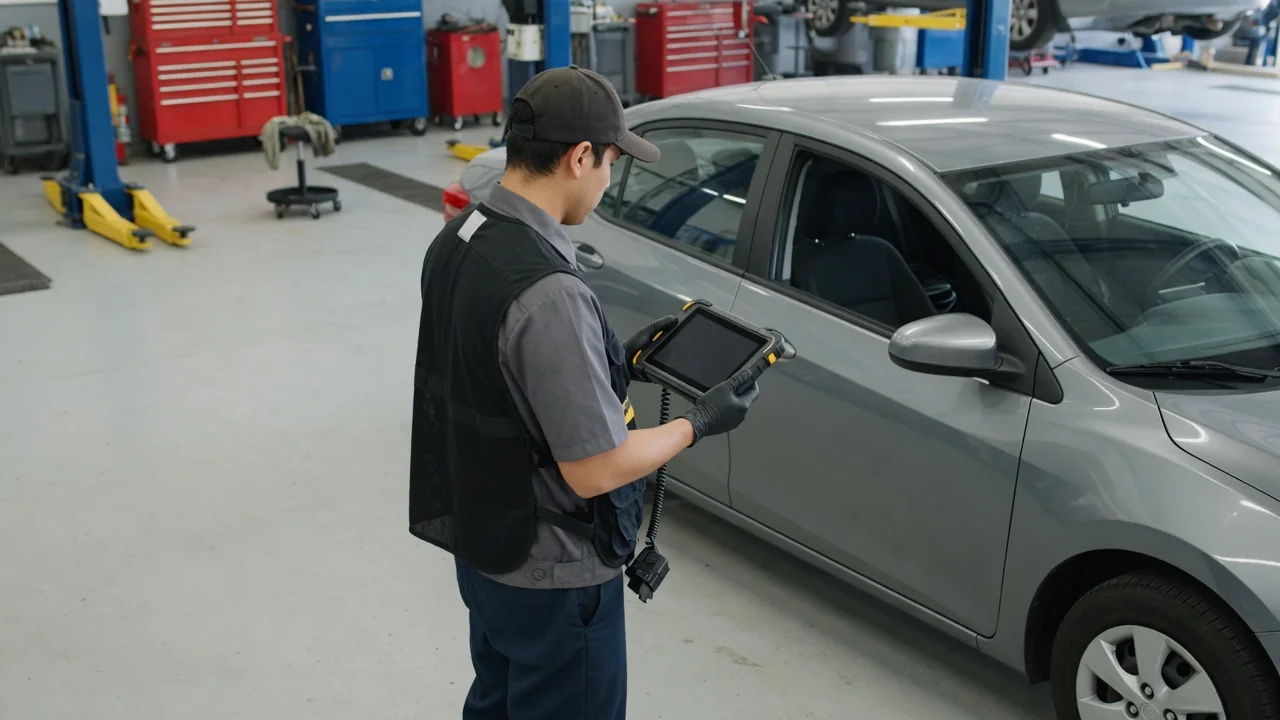
The P1860 code is a manufacturer-dependent diagnostic trouble code that commonly points to a torque converter clutch pulse-width modulation solenoid circuit condition, though that meaning is not universal. Confirm the definition using year, make, model, transmission, and service information before drawing conclusions. A circuit code identifies a monitored electrical condition rather than proving a part has failed. Record the scanner description, P1860 symptoms, and companion codes so diagnosis starts from the actual stored context.
Confirm What P1860 Means for Your Vehicle
P1860 is not a single industry-wide definition, so the first task is to match the stored code to the vehicle in front of you. Year, make, model, engine, and transmission family all matter because manufacturers reuse numeric identifiers for different monitored circuits. Service information for that combination is the source that tells you whether this P1860 code refers to a torque converter clutch PWM solenoid circuit or to another transmission function. Reading the exact scanner text, including any manufacturer-specific wording, keeps interpretation aligned with the control strategy actually used on that application.
On vehicles where service information assigns that meaning, P1860 commonly describes an electrical circuit fault involving the TCC PWM solenoid, which the transmission control module uses to modulate converter clutch apply. That still does not mean the solenoid itself has failed. Circuit monitoring compares commanded control with expected electrical behavior, so an open, short, or unexpected voltage can set the code while the valve and clutch remain mechanically sound. Capture every companion code, the freeze-frame snapshot, and the precise scan-tool description so later tests address the monitored path rather than a guessed part.
How the Torque Converter Clutch PWM Circuit Works
When the verified definition is a torque converter clutch PWM circuit, the clutch inside the converter is intended to reduce slip once the transmission control module judges conditions appropriate. At lighter cruise, locking the converter couples engine and transmission more directly, which can stabilize engine speed and reduce heat generated by fluid shear. Pulse-width modulation is the electrical method used to vary how long the TCC PWM solenoid is energized during each control cycle. Changing that duty cycle allows the module to ramp clutch apply instead of slamming the clutch fully on or off.
The controller, often the transmission control module, commands the solenoid through a vehicle-specific driver circuit. Power, ground, and signal travel through the transmission wiring harness and connectors, whose layout differs by application. The solenoid meters hydraulic pressure that applies the clutch, but the circuit monitor watches electrical behavior, not clutch torque. Clutch slip data describe driveline action, while a circuit code describes the electrical path. Those views can disagree, so a P1860 electrical finding is not proof of converter clutch failure.
Symptoms That May Accompany P1860
P1860 symptoms vary with how the control module responds once it detects the circuit condition. Many drivers first notice an illuminated malfunction indicator or transmission warning lamp, sometimes with a stored code and little else. Where the module limits torque converter clutch apply, steady-speed cruise may show higher engine rpm than expected because the converter continues to slip. Engagement can feel delayed, abrupt, or inconsistent when pulse-width modulation no longer ramps the clutch as designed. On other vehicles the driver notices no drivability change beyond the lamp, because the electrical fault is recorded without a large change in clutch strategy.
Shudder during light throttle, unusual shift feel, or reduced fuel economy can appear around converter clutch events, yet those complaints have many other origins, including engine misfire, mount issues, and hydraulic wear. They cannot confirm a TCC PWM solenoid circuit problem by themselves. Note when any change happens: cold or fully warm, city traffic or highway, after a stop, or only at a particular speed. Record temperature, gear, and driving conditions without trying to force the fault. That timeline, together with freeze-frame data, helps a technician compare P1860 symptoms with commanded clutch activity instead of chasing unrelated drivability issues.
Possible Causes Behind a Verified TCC Circuit Fault
Once service information confirms a TCC PWM circuit assignment, attention belongs on the electrical path the module actually monitors. Chafed wiring in the transmission wiring harness, stretched terminals, water intrusion, and corrosion at case connectors can interrupt power, ground, or the control signal. Those problems can appear intermittent as the harness flexes with temperature and movement. An electrical fault inside the TCC PWM solenoid, such as an open coil or internal short, can also set circuit monitoring. That still requires measurement against the correct diagram, because the code does not identify which end of the circuit failed.
A failed driver inside the transmission control module can produce the same electrical circuit fault, yet module replacement is justified only after wiring, connectors, power, and ground prove sound. Controller faults are possible, not presumed. Burned, contaminated, or low fluid can change clutch apply feel, and a worn torque converter clutch can create slip visible in scan data. Those mechanical and fluid conditions still do not explain why circuit monitoring set P1860. Treat hydraulic and clutch findings as separate evidence that may coexist with, rather than replace, an electrical diagnosis.
Safe Observations and Professional Diagnostic Tests
Save all stored codes and available freeze-frame data before clearing anything. Freeze-frame data captures operating conditions when P1860 set, including related clutch slip data if the tool reports them, and clearing erases that context. Owner checks should stay limited: note dashboard warnings, write down symptoms, and look for obvious leaks or damaged connectors from a safe stance with the vehicle parked and supported. Stay away from hot exhaust, converters, and transmission surfaces, and do not work beneath an unsupported vehicle. Do not probe live circuits or command solenoids as a do-it-yourself step.
A technician uses the matching wiring diagram and specifications to evaluate circuit integrity, supply voltage, grounds, connector condition, and solenoid electrical behavior. Supported scan-tool commands and clutch operating data can show whether the module can control the TCC PWM solenoid and whether apply matches command, without substituting for electrical tests. Continuity on a cold, unflexed harness may miss an intermittent or load-dependent electrical circuit fault that appears only when the circuit is powered, hot, or moving. Those distinctions keep diagnosis focused on the monitored path rather than replacing the solenoid without electrical proof.
Repair Decisions, Driving Limits, and Verification
Repair should follow confirmed findings, which may mean restoring a connector, repairing the transmission wiring harness, servicing the TCC PWM solenoid, or continuing controller diagnosis if the driver circuit is at fault. The P1860 code alone cannot identify a compatible part, solenoid design, or labor path, because access and internal layout differ by transmission. There is no universal assurance that the vehicle is safe to keep driving. Seek prompt assessment, and stop safely if severe slipping, loss of drive, overheating warnings, or a burning smell develops, since those signs can indicate a worsening driveline or thermal problem.
After any repair, verification must follow the vehicle-specific procedure, not a cleared lamp. Recheck for returning codes, compare commanded pulse-width modulation with clutch slip data, and confirm that converter clutch apply occurs under the conditions the manufacturer uses for that test. A warning light that stays off after a code erase only shows the monitor has not yet failed again; it does not prove the electrical circuit fault is gone or that the torque converter clutch is applying correctly. Document the completed tests so the original P1860 condition is shown resolved rather than merely hidden.