P0337 and P0338: Crankshaft Position Sensor Low and High Input
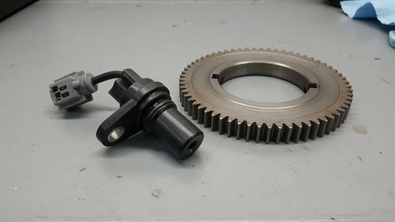
When the engine computer logs P0337 or P0338, the crankshaft position sensor circuit is reporting an electrical signal outside its expected range. P0337 indicates low input, while P0338 indicates high input. Both codes point to the same fundamental concern: the engine speed signal from the CKP sensor circuit is not reaching the control module in a usable form. Interpreting these fault codes requires understanding signal voltage, reluctor wheel operation, and how a wiring fault or connector issue can imitate a sensor failure before any parts are replaced.
What P0337 Means for the Crankshaft Sensor Circuit
P0337 is the generic crankshaft position sensor A circuit low-input code, though the exact wording and setting criteria must be confirmed for the specific year, make, model, and engine. The control module determines that the CKP sensor circuit's electrical signal has fallen below a calibrated threshold under specified monitoring conditions. This low-input condition does not describe engine speed that is too low, nor does it prove that the sensor itself has failed. Instead, it is a starting point for checking why the circuit voltage is being pulled down or interrupted.
Before applying any circuit specifications or identifying which sensor is designated as sensor A, the exact vehicle configuration must be known. Different engine families use different crankshaft position sensor types, connector pinouts, and wiring harness routing. A low-input code can arise from an open circuit, excessive resistance, a short to ground, or a failing sensor supply voltage. The reluctor wheel and its air gap can also influence the signal amplitude, so vehicle-specific service information is necessary to interpret the code correctly.
What P0338 Means for the Crankshaft Sensor Circuit
P0338 is the companion generic code for crankshaft position sensor A circuit high-input, and it likewise requires confirmation of the vehicle-specific description and setting criteria. High input refers to the monitored electrical signal being above the expected voltage or frequency threshold under defined operating conditions. It does not mean that engine speed is excessive. The control module monitors the CKP sensor circuit continuously while the engine is running, comparing the signal against a learned or programmed reference. When the signal remains too high for too long, the code is stored.
The sensor design and circuit layout determine which electrical faults can trigger a high-input code. For example, a Hall-effect sensor may produce a high-input condition if its signal wire is shorted to a reference voltage or if the sensor's internal pull-up resistor is compromised. A magnetic inductive sensor, which generates its own AC voltage, may set a high-input code if the reluctor wheel is damaged or if interference couples into the wiring. The code alone cannot identify the failed component; it only indicates that the circuit's electrical signature has exceeded the expected upper boundary.
Symptoms and When to Stop Driving
A vehicle with P0337 or P0338 may exhibit hard starting, a crank-no-start condition, stalling, irregular running, and an illuminated malfunction indicator lamp, though not every vehicle will show all symptoms. Because the crankshaft position sensor provides the primary engine speed signal used for ignition timing and fuel injection, a corrupt or missing signal can prevent the engine from starting or cause it to stall without warning. Intermittent electrical faults may leave the engine running normally between episodes, making the problem difficult to duplicate during a quick inspection.
If the engine stalls, loses power, or cannot run reliably, the vehicle should be stopped safely and professional assistance arranged. A stored code alone cannot establish whether continued driving is safe, because circuit conditions can change with temperature, vibration, or moisture. A vehicle that starts and runs normally at the time of diagnosis may still have an intermittent wiring fault that could cause sudden stalling in traffic. Therefore, the prudent course is to treat any active crankshaft sensor circuit code as a potential driveability and safety concern until the circuit has been inspected and tested.
Fault Sources That Need Confirmation
Damaged wiring, connector corrosion, loose terminals, and circuit faults are common possibilities for both P0337 and P0338, though their effects depend on the specific wiring design. A chafed wire rubbing against a bracket may intermittently short the signal to ground, producing a low-input code. Conversely, a wire that intermittently contacts a battery voltage source may produce a high-input code. Sensor connector issues, such as a spread terminal or a broken locking tab, can allow the signal to drop out when the engine moves on its mounts. These mechanical faults are often overlooked when the sensor itself is blamed prematurely.
Sensor supply, ground, or internal sensor problems require testing appropriate to the installed sensor type. A Hall-effect CKP sensor needs a clean supply voltage and a solid ground to produce a usable square-wave signal, while a magnetic inductive sensor relies on the reluctor wheel passing close enough to generate a sufficient AC voltage. Sensor mounting and reluctor condition should be investigated only where vehicle-specific information supports doing so, because access and inspection procedures vary. Control-module failure is always a possibility, but it requires supporting evidence such as confirmed good wiring and sensor operation with no signal reaching the module, not a conclusion drawn from either code on its own.
Useful Information to Gather Before Testing
Before testing begins, record all stored and pending codes together with the available freeze-frame data. Freeze-frame information captures the operating conditions present when the fault was detected, such as engine speed, coolant temperature, and load. This data can help identify whether the problem occurs during starting, after warming up, or under specific driving conditions. Do not clear anything until this information has been documented, because clearing codes erases the freeze-frame snapshot and may reset readiness monitors, making intermittent faults even harder to diagnose.
Note whether the problem occurs during starting, after warming up, or intermittently, and record any recent repairs or battery trouble. A weak battery or a recent jump start can generate voltage spikes that affect sensor readings. Owner observations should be limited to accessible wiring and connectors with the engine off and cool, avoiding moving parts, hot components, and accessing beneath an unsupported vehicle. Scan-tool engine-speed data may provide a clue, but its presence or absence does not independently prove a sensor fault, because the control module may substitute a default strategy or may be receiving an invalid signal that the scan tool interprets as zero or erratic RPM.
Professional Circuit Testing and Repair Verification
Professional circuit testing requires the correct wiring diagram, sensor identification, and manufacturer diagnostic procedure before any electrical measurements are made. A technician will check circuit integrity, applicable power and ground feeds, and signal behavior using the appropriate tools, but this must be done without unsafe probing, bypassing, or live-engine repair shortcuts. The wiring diagram shows how the CKP sensor circuit is routed, which connector pins serve which function, and where the signal is shielded or spliced. Comparing the actual measured values against the manufacturer's specifications is the only reliable way to isolate a wiring fault from a sensor or module fault.
Waveform testing and checks for intermittent faults can help locate a problem that a single voltage reading may miss. A lab scope or graphing multimeter can display the sensor's signal as the crankshaft rotates, revealing missing pulses, amplitude changes, or noise that only occurs under load or at temperature. Wiggling the harness while monitoring the signal can expose a poor connection. After any repair, verification requires appropriate operating checks and a rescan for returning codes. Clearing codes alone does not confirm a repair; the vehicle must be driven through the conditions that originally set the fault, and the control module must complete its self-test without logging the code again.