P0330–P0334: Bank 2 Knock Sensor Circuit Codes
A P0332 code, or any related code from P0330 through P0334, means the engine computer detected a problem in the bank 2 knock sensor circuit. These codes describe the signal path. They don't prove that a part has failed or that the engine actually knocked. Knowing what each code generally means, which symptoms need attention, and how a technician confirms the fault can keep you from buying parts the car never needed.
P0330 and the Vehicle’s Bank 2 Knock Sensor Circuit
Before you interpret any code in this family, confirm the exact description and diagnostic procedure for your vehicle's year, make, model, and engine. Manufacturers can define the details differently. The standard generic meaning of a P0330 code is a malfunction in the knock sensor 2 circuit on bank 2. Some engines use one sensor per bank, while others use several sensors or a different numbering scheme. The vehicle's service documentation decides which physical sensor and which wiring the code refers to.
Bank 2 is the cylinder bank that does not contain cylinder 1. This matters on V-type and horizontally opposed engines. Whether it sits on the left or right varies, so check engine-specific information instead of guessing. The knock sensor picks up vibration so the engine control module can detect combustion knock and retard ignition timing to protect the engine. A circuit code only means the module judged the signal or circuit to be abnormal. By itself, it can't identify a failed component or confirm that knock happened.
P0331 Range/Performance and P0332 Low Input
If your vehicle uses the standard definition, a P0331 code means knock sensor 2 circuit range/performance on bank 2. Usually this means a signal is present but doesn't behave as the module expects under certain operating conditions. A P0332 code is the standard low-input description: the monitored circuit signal fell below what the module considers plausible. The manufacturer sets the threshold and the conditions under which the test runs, so no single voltage figure applies to every engine or every sensor design.
Several factors can matter, depending on the vehicle's diagnostic procedure. A sensor that isn't seated properly against its mounting surface may pass vibration poorly, which weakens its output. Chafed insulation, a stretched wire, or a poor connection can reduce signal strength or create an open or short in the knock sensor circuit. Neither P0331 nor P0332 tells you whether audible engine knock is present or absent. Neither one justifies installing a new sensor on its own; testing has to show where the problem is.
P0333 High Input and P0334 Intermittent Signal
The standard description of a P0333 code is knock sensor 2 circuit high input on bank 2, meaning the module saw a signal above its expected range. As with every code in this group, confirm that definition against the vehicle's service information. A P0334 code describes an intermittent circuit condition, where the signal drops out or turns erratic only some of the time. That explains a common frustration: the fault may be gone when a shop first looks at the car, and the connector can look normal until conditions line up again.
Connector terminals with weak contact tension, a wiring harness rubbing against a bracket, or an internal sensor defect can each distort the signal, and none of them produces one universal electrical pattern. A loose terminal might cause dropouts only on rough pavement, while heat damage might show up only after warm-up. That's why recorded temperature, engine load, speed, and other operating conditions are so useful. Freeze-frame data and notes about when the warning comes back help a technician reproduce a recurring fault instead of chasing it at random.
Symptoms and Signs That Need Prompt Attention
The most common sign is an illuminated malfunction indicator, and many drivers notice nothing else. Others report reduced power, hesitation when accelerating, or changed fuel consumption. Whether the engine retards ignition timing to protect itself depends on the vehicle's control strategy. Some systems switch to more conservative timing when the knock signal can't be trusted, while others respond differently. Hesitation and poor fuel economy have many possible causes, so these symptoms can't tell you which sensor, connector, or wire needs repair.
Some situations need prompt action. Stop safely as soon as you can and arrange help, rather than driving on, if you have any of these: severe knocking or pinging, a temperature gauge climbing toward overheating, a flashing malfunction indicator, or a major loss of power. Don't deliberately put load on the engine to see whether the knocking gets worse or the light comes back. A steady light with normal driving is less urgent, but it still deserves diagnosis soon, because the engine's knock protection may not work properly while the fault continues.
Sensor, Connector, and Harness Causes to Investigate
Possible causes include a failed sensor, connector corrosion, moisture getting into the connector or harness, loose connections, and damaged wiring. Treat each one as a possibility that needs evidence, not an assumption. Sensor mounting can also matter, because the sensor needs firm contact with the engine to pick up vibration. Details like mounting surface condition, fastener torque, and required hardware come from vehicle-specific service information, not general rules. If a replacement sensor was installed recently, how it was installed is worth knowing.
Write down any recent engine work, especially jobs that required removing the intake manifold or other parts near the sensors, and when the warning first appeared. That timing is useful context but doesn't prove cause: a harness disturbed during service might be involved, or the timing might be a coincidence. Limit your own inspection to areas you can see safely with the engine off and cool. Look for rodent damage, melted insulation, or an unplugged connector in plain view. Leave hidden connectors, component removal, and electrical probing to a qualified technician.
Professional Diagnosis and Repair Verification
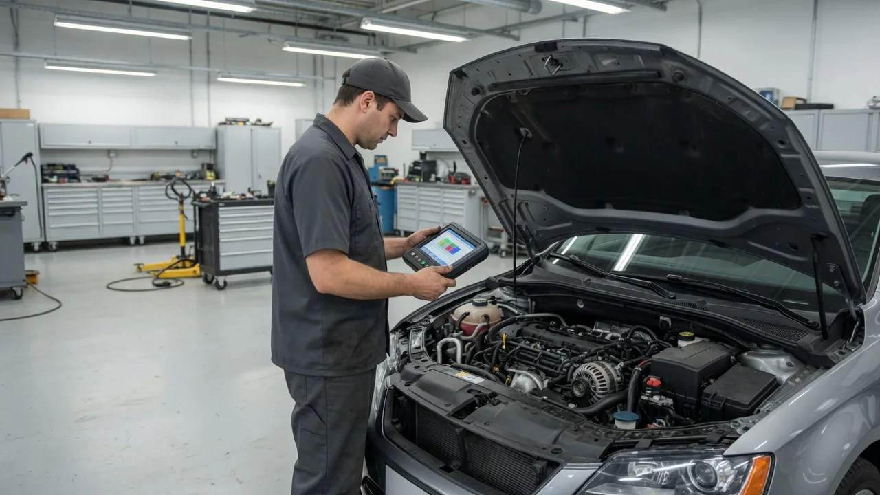
A technician starts by recording all stored and pending codes and the freeze-frame data before clearing anything. That snapshot shows temperature, load, and speed at the moment the fault set, and clearing codes erases it. Related codes for the bank 1 sensor or shared circuits can point to a common wiring issue or a control module concern. The next step is the vehicle-specific wiring diagram and test procedure. These show the affected circuit, the connector pins, the wire routing, and the checks the manufacturer expects before any part is condemned.
Professional testing usually checks the sensor signal with a scan tool or oscilloscope, then checks the circuit for opens, shorts, and unwanted resistance. The values and methods come from service information, not universal numbers or improvised tests. The repair should follow what testing confirms, whether that is a new sensor, a terminal or connector repair, or harness work. To verify the repair, the technician checks the fault status and confirms the related monitor completes under the manufacturer's required conditions. A cleared warning light proves nothing; if the code returns, the root cause is still there.