P0171, P0174 and P0300 Together: Diagnosing Lean Conditions and Misfires
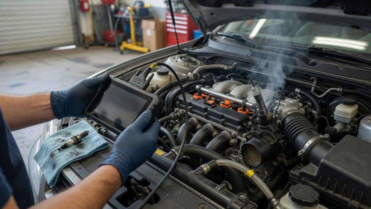
Direct answer: the three codes usually point to one shared fault
When P0171, P0174 and P0300 are stored together, the most useful first interpretation is that the engine is running lean on both cylinder banks and has also recorded a random or multiple-cylinder misfire. P0171 means the powertrain control module saw a lean air-fuel condition on bank 1, while P0174 means the same condition was detected on bank 2. P0300 means misfires were detected across more than one cylinder or in a pattern that the module could not assign to one specific cylinder. A shared cause affecting both banks is more likely than two independent bank-specific failures, so diagnosis should normally begin with air intake, crankcase ventilation, fuel delivery and exhaust-related faults that can affect the whole engine.
The exact repair is not universal. Vehicle age, engine configuration and market-specific emission systems change which components are likely. For example, a vacuum leak may be concentrated in an intake manifold gasket on one engine family, while another engine may be more affected by a failed PCV hose or a contaminated mass airflow sensor. Use live data and targeted tests to identify the fault before replacing parts.
What the codes mean
P0171 — System Too Lean Bank 1: The fuel mixture has too much air or too little fuel on the bank containing cylinder 1. P0174 — System Too Lean Bank 2: The same lean imbalance is detected on the opposite cylinder bank. P0300 — Random/Multiple Cylinder Misfire Detected: The engine is misfiring on changing cylinders or on enough cylinders that one specific cylinder cannot be identified.
On V-type and other multi-bank engines, seeing P0171 and P0174 together is significant because the engine computer is calculating too much fuel correction for both banks. The simultaneous P0300 may be the symptom of that lean mixture causing weak or unstable combustion, but misfires can also be the original problem: unburned oxygen from a misfiring cylinder can enter the exhaust and make an oxygen sensor report a false lean condition.
Why oxygen from misfires can create a lean-code illusion
A misfire leaves unburned fuel and unused oxygen in the exhaust. The upstream oxygen or air-fuel ratio sensor responds strongly to oxygen, so a cylinder that is not firing can make the sensor see a lean mixture even when the injector delivered enough fuel. The control module then raises fuel trim to compensate. This is why a genuine ignition, injection or compression fault can be accompanied by lean codes, and why clearing the codes without checking misfire data may lead to the wrong repair.
Start with freeze-frame data and fuel trims
Freeze-frame data shows the engine conditions present when the fault was recorded, including coolant temperature, engine speed, load and fuel-trim values. Short-term fuel trim, or STFT, is the immediate correction being applied by the control module. Long-term fuel trim, or LTFT, is the learned adjustment developed over time. A useful early test is to compare fuel trims at idle with fuel trims at higher RPM under load.
If LTFT is strongly positive at idle and improves toward normal at higher RPM, suspect an idle-dominant vacuum leak or an unmetered-air path such as a cracked PCV hose. If LTFT stays positive across idle and load, suspect a wider air leak, a mass airflow sensor underreporting airflow, or a fuel delivery limitation. If STFT is erratic and the misfire counter is active, confirm whether the misfire is creating the lean reading before treating the lean condition as the root cause.
Common shared causes affecting both banks
Because P0171 and P0174 appear on both banks, prioritise components and leaks that are shared by the whole engine. These include the air intake duct between the mass airflow sensor and throttle body, crankcase ventilation passages, purge-valve plumbing and any large vacuum circuit such as the brake booster.
Unmetered air and vacuum leaks
Unmetered air is air that enters the engine without being measured by the mass airflow sensor. The control module then injects fuel for a smaller air mass than the engine actually receives, producing a lean mixture. Intake manifold gaskets are a common source on engines where the manifold mates to the cylinder heads, but cracked hoses, loose clamps and split intake boots can produce the same result.
A smoke test is often the most direct method of locating a vacuum leak. Pressurised smoke is introduced into the intake system, and any escaping smoke identifies the leak path. Do not assume the leak is near the code-related bank; a single shared leak can influence both banks.
Positive crankcase ventilation system
The positive crankcase ventilation, or PCV, system routes crankcase vapours into the intake. A failed PCV valve, broken hose or disconnected fitting can allow extra air into the intake manifold. Because PCV flow enters a shared intake path, it can raise fuel trim on both banks and mimic a general vacuum leak.
EVAP purge valve
The EVAP purge valve allows stored fuel vapour to enter the engine during appropriate conditions. A purge valve that is stuck open, or a purge path that admits air when it should be closed, can act as another unmetered-air source. Diagnosis should consider whether the lean condition changes when the purge valve is commanded closed during a scan-tool function test.
Brake booster vacuum circuit
The brake booster uses engine vacuum. A leaking booster diaphragm, hose or check valve can create a sizable vacuum leak. In some cases the leak may be audible or may change when the brake pedal is applied, making it useful to test the booster circuit as part of a shared-leak search.
Mass airflow sensor and intake duct
A contaminated or failing mass airflow, or MAF, sensor can underreport the air entering the engine. The control module then injects too little fuel, creating a lean condition across the engine. Leaks after the MAF sensor are equally important because they let air enter without being measured. Check the intake duct for splits, poor sealing or a loose connection before condemning the sensor. MAF-sensor values should also be compared with a known-good range for the specific engine, not with a generic universal number.
Fuel pressure, volume and injectors
Low fuel delivery can make both banks lean. A restricted fuel filter, a weak fuel pump or a pressure regulator fault may reduce pressure, while a volume test can reveal a pump that provides pressure but cannot maintain flow under demand. Fuel pressure and volume specifications vary by engine, so use the vehicle manufacturer's test values for the relevant model year and configuration.
Fuel injectors can also contribute when they are restricted or not delivering evenly. If live data shows that one bank requires much more correction than the other, bank-specific injector or oxygen-sensor testing becomes more important. However, the three-code pattern still favours checking shared supply and shared air paths first.
Oxygen, air-fuel ratio sensors and exhaust leaks
Upstream oxygen and air-fuel ratio sensors provide the feedback used for fuel correction. A sluggish or biased sensor can cause inaccurate fuel trim, but the sensor itself should not be replaced simply because a lean code is present. Compare the sensor signal with the actual operating condition and with any measured exhaust or fuel-trim response.
Exhaust leaks upstream of the sensors are also relevant. Outside air drawn into the exhaust near an upstream sensor can dilute the exhaust sample and create a false lean reading. The leak may not be large enough to be heard, so inspect flanges, gaskets and pre-sensor joints when fuel-trim behaviour does not match the expected intake-leak pattern.
Misfire diagnosis: ignition, injection and compression
Because P0300 is a random or multiple-cylinder misfire code, the misfire counter can show which cylinders are involved and whether the fault moves or remains concentrated. Spark plugs and ignition coils that are worn or failing can cause misfires under load or at idle, and may be shared or cylinder-specific depending on the ignition design.
Inspect spark plugs for wear, fouling or damage and compare their condition across cylinders. Use the misfire counters to decide whether testing should focus on specific coils, injectors or cylinders. Check fuel injector operation where a cylinder is not contributing combustion. Perform a compression test or a valve-timing check when mechanical damage, a failed head gasket or a timing fault is suspected.
Compression and valve timing faults are less common than air and fuel delivery faults, but they are important when the misfire does not respond to ignition or fuel repair. If compression is uneven or a timing-related code or symptom is present, mechanical diagnosis should not be skipped.
Suggested diagnostic order
Read freeze-frame data and record STFT and LTFT at idle and under load. Check the misfire counters to determine whether the misfire is random, moving or cylinder-specific. Inspect the intake duct, PCV system, purge path and visible vacuum lines for obvious leaks or disconnections. Perform a smoke test of the intake system to find smaller leaks. Check MAF-sensor data and the surrounding intake seal for plausibility. Test fuel pressure and volume according to the manufacturer's specification. Evaluate upstream oxygen or air-fuel ratio sensor response and inspect for pre-sensor exhaust leaks. If the misfire remains unexplained, test ignition, injectors, compression and valve timing.
Post-repair verification
After a repair, clear the codes and allow the engine to complete the relevant drive cycle required by the vehicle. Watch LTFT return toward a normal range rather than focusing only on whether the light stays off. Confirm that the misfire counters no longer increase and that both banks show similar fuel-trim behaviour. A code that does not return is useful, but fuel-trim and misfire data are better evidence that the underlying operating fault has been corrected.
What is still uncertain without vehicle-specific data
The exact component to replace cannot be identified from the three codes alone. Engine layout, model-year emission hardware, fuel-system design and the recorded operating conditions all affect the likely fault. A vehicle with an external leak, a restricted fuel filter or a weak pump may show the same three codes as a vehicle with a contaminated MAF sensor. Live data, visual inspection and targeted pressure or smoke tests are required to distinguish the possible causes.