P0075–P0086: Intake and Exhaust Valve Control Solenoid Circuit Codes
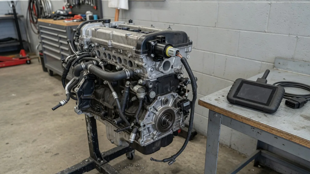
Codes P0075 through P0086 describe electrical faults in intake and exhaust valve control solenoid circuits used with variable valve timing. Standard wording identifies the circuit, bank, and whether the control module saw a circuit low or circuit high condition. A stored P0075 code or related code is evidence to interpret, not proof a solenoid has failed. Confirm the exact description and diagnostic path for the vehicle's year, make, model, and engine before acting on scanner text.
P0075, P0076, and P0077: Bank 1 Intake Valve Control Circuit
Before treating any P0075 code, P0076 code, or P0077 code as a parts list, match the scanner wording to the manufacturer's description for that year, make, model, and engine. In common labeling, P0075 identifies the bank 1 intake valve control solenoid circuit, P0076 specifies circuit low, and P0077 specifies circuit high. Similar numbering can still map to different layouts and enable conditions, so a generic reading can send testing to the wrong connector.
Bank identification starts with cylinder 1: bank 1 contains that cylinder, while the physical side depends on the engine. Locating the correct intake valve control solenoid therefore needs engine-specific information. An electrically controlled solenoid participates in valve timing control, though design varies by engine, often by metering oil so the module can change camshaft timing. Circuit low and circuit high describe the electrical condition monitored on the solenoid control signal, not oil level, engine speed, or valve position.
P0078, P0079, and P0080: Bank 1 Exhaust Valve Control Circuit
A P0078 code, P0079 code, or P0080 code points to the bank 1 exhaust valve control solenoid circuit rather than the intake path on the same bank. In standard wording, P0078 identifies that exhaust circuit, P0079 specifies circuit low, and P0080 specifies circuit high. Intake and exhaust solenoids can sit close together with similar connectors, so confirming the bank 1 exhaust valve control solenoid matters before testing or ordering parts.
A circuit code alone does not establish whether the solenoid, wiring harness, connector, power supply, ground, or control electronics produced the fault. The module reports that the monitored electrical condition fell outside its expected range, which can result from an open, a short, high resistance, or a driver issue. Check the vehicle-specific circuit layout and the conditions that set P0078, P0079, or a P0080 code before treating scanner wording as a failed part.
P0081, P0082, and P0083: Bank 2 Intake Valve Control Circuit
In standard descriptions, a P0081 code identifies the bank 2 intake valve control solenoid circuit, a P0082 code specifies circuit low, and a P0083 code specifies circuit high. Those labels belong to the cylinder bank that does not contain cylinder 1. On a V-type engine that bank has a distinct physical location; on an inline engine the same numbering can confuse a generic chart. Verify the selected engine and scanner description if the reported bank does not match the layout.
If the reported bank still does not match the engine, confirm the VIN-based engine and the exact code text rather than swapping solenoids by habit. An intermittent P0081, P0082, or P0083 fault can store a code after a brief open, short, or poor connection, then the engine may currently run without a noticeable drivability change. Heat, vibration, and connector movement can recreate the same electrical condition after the warning light first appeared.
P0084, P0085, and P0086: Bank 2 Exhaust Valve Control Circuit
Standard wording treats a P0084 code as the bank 2 exhaust valve control solenoid circuit, a P0085 code as circuit low, and a P0086 code as circuit high. Those exhaust labels sit on the bank without cylinder 1, so solenoid and connector identification still depend on the exact engine. Confirm that location from manufacturer information rather than assuming the same side as bank 1 hardware. Mixing bank 2 exhaust with bank 1 exhaust or a bank 2 intake solenoid is a frequent identification error.
Circuit high or circuit low wording cannot, by itself, identify an open wire, a short to power or ground, a corroded pin, or a control-module driver. Record other stored and pending codes because several valve control circuits may share a fused supply, a ground splice, or a common connector. A companion P0075, P0078, P0081, or P0086 condition on another circuit can point toward that shared feed rather than four independent solenoid failures.
Symptoms and Signs That Require Stopping
A P0075 through P0086 event may turn on a check-engine light with rough idle, hesitation, reduced power, or no obvious drivability change. Not every vehicle develops those running complaints, and some store a P0076, P0079, P0082, or P0085 code after a brief electrical glitch the driver never felt. Symptoms cannot identify the affected bank, the intake or exhaust solenoid, or whether wiring, a connector, or control electronics caused the reading.
Stop safely and seek assistance for an oil-pressure warning, severe engine noise, stalling, or a flashing check-engine light with rough running. Those signs can indicate conditions that risk further engine damage and are not explained by a circuit label alone. A steady warning light also does not establish that continued driving is safe. Severity, other warnings, unusual noises, and the vehicle's own guidance determine the next step. Loss of commanded camshaft timing can change drivability quickly even when the stored code described only an electrical range problem.
Possible Causes and Safe Owner Observations
Possible electrical causes include damaged wiring, a loose or corroded connector, a solenoid winding fault, a missing supply or ground, or a control-module driver problem, each of which still requires evidence. Oil condition and hydraulic timing problems can change variable valve timing behavior, yet a P0077 code, P0080 code, P0083 code, or P0086 code reports an electrical range, not a stuck cam phaser. Those circuit codes alone do not prove an oil-related cause, so do not replace a solenoid only because its name appears in the description.
Check oil level only through the owner's manual procedure, then record recent oil changes and any nearby engine work that could have disturbed a wiring harness. Limit visual observations to readily accessible areas with the engine off and cool. Note visible insulation damage, rubbed loom, or leaks around a solenoid body without unplugging, probing, or dismantling components. Notes about when the light appeared, after a wash, after repairs, or only when hot, help later testing without creating new faults.
Professional Circuit Testing and Repair Verification
Preserve stored, pending, and freeze-frame data before clearing codes. Freeze-frame data captures operating conditions when the fault was detected, including whether the solenoid control signal was being commanded, which later testing can try to recreate. A technician uses vehicle-specific wiring information and the published diagnostic procedure to evaluate circuit integrity, supply, ground, and control. Powered circuit tests, direct solenoid activation, connector probing, and engine disassembly belong in that professional sequence.
Commanded solenoid operation compared with camshaft response data can show whether the electrical circuit and the hydraulic timing hardware are both responding. Electrical findings should guide any further hydraulic or mechanical investigation rather than the reverse. After a repair, confirmation follows the manufacturer's verification procedure, including code status and whether original symptoms remain. Clearing a warning light is not proof the P0075, P0078, P0081, or P0084 circuit is healthy if the same circuit high or circuit low condition can return.