P0053–P0055 and P0059–P0061: Oxygen Sensor Heater Resistance Codes
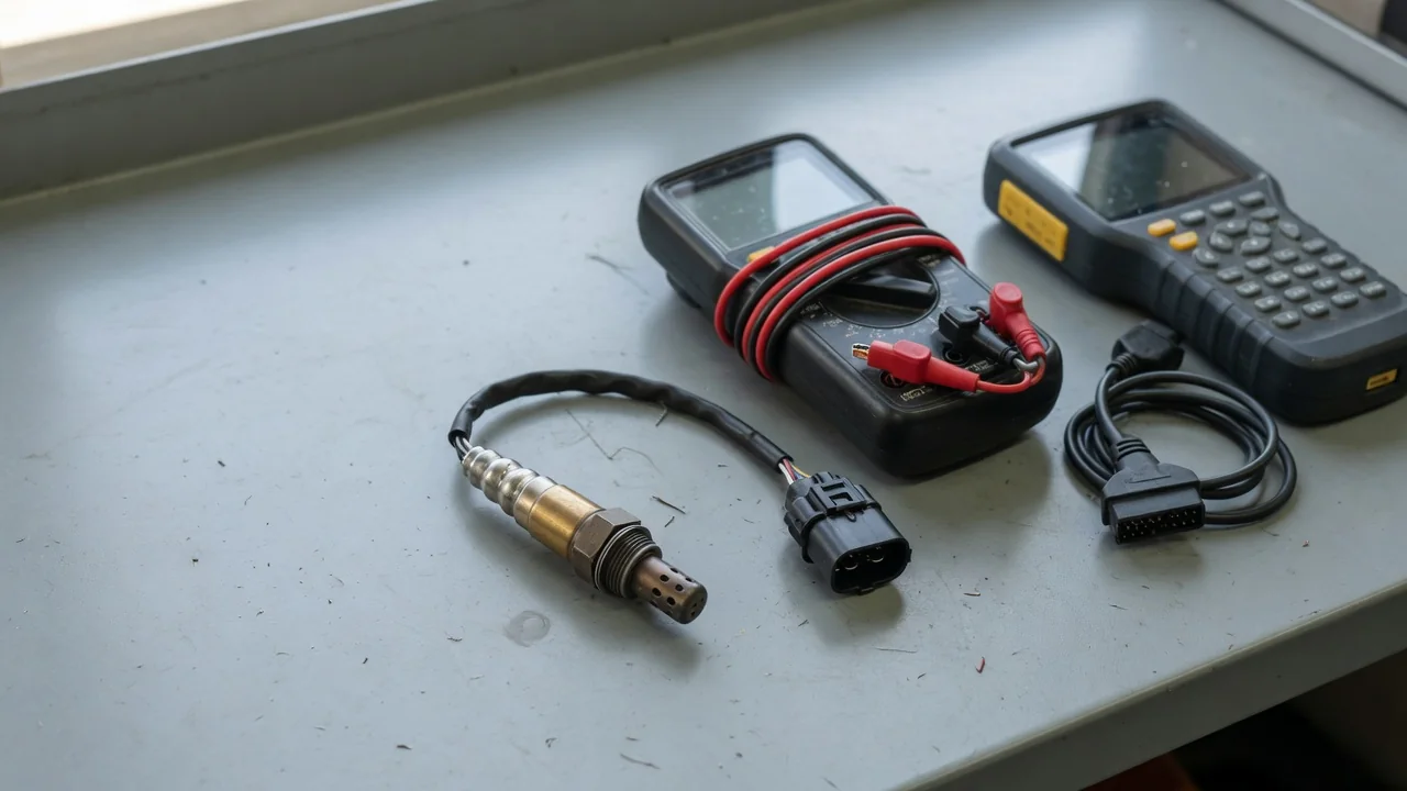
P0053 through P0055 and P0059 through P0061 flag oxygen sensor heater resistance conditions on bank 1 and bank 2. These codes describe a monitored electrical property of the heated oxygen sensor heater, not a finished diagnosis. Scan-tool wording, sensor position, and the exact procedure still depend on the vehicle. Interpreting the stored evidence, related symptoms, and heater-circuit checks comes before any parts decision.
P0053, P0054 and P0055: Bank 1 Heater Resistance Codes
On many powertrains the P0053 code maps to bank 1 sensor 1 heater resistance, the P0054 code to bank 1 sensor 2, and the P0055 code to bank 1 sensor 3. That mapping is a useful starting point, not a substitute for the vehicle's published description. Before treating scan-tool wording as a parts list, confirm the exact definition and the diagnostic procedure written for that application. Manufacturer-dependent wording can differ, and a shared label does not guarantee an identical circuit layout.
Bank 1 is the cylinder bank that contains cylinder 1, yet the physical sensor position still has to be taken from that vehicle's service information and exhaust layout. Sensor 1 is typically upstream of the catalyst and sensor 2 downstream, while a third heated oxygen sensor appears only on some exhaust designs. A P0053, P0054, or P0055 result records a detected heater-resistance condition. It is evidence to interpret, not independent proof that the sensor itself must be replaced.
P0059, P0060 and P0061: Bank 2 Sensor Positions
The P0059 code commonly concerns bank 2 sensor 1 heater resistance, the P0060 code bank 2 sensor 2, and the P0061 code bank 2 sensor 3. Bank 2 is the opposite bank from cylinder 1 on engines that actually have two banks. Inline engines and some exhaust layouts do not present a second bank at all, so a reported bank 2 position should be checked against vehicle identification and the installed engine before any component is assumed.
Use the vehicle's exhaust diagram to establish each sensor position rather than assuming every powertrain has a second bank or a third heated oxygen sensor. When the reported position looks inconsistent with the engine and exhaust that are actually fitted, stop and confirm code interpretation for that VIN and calibration. The same caution applies as on bank 1: a heater resistance code describes an electrical condition the monitor observed. It does not, by itself, prove which part in the heater circuit is at fault.
Symptoms and What They Can Tell You
P0053 symptoms and P0054 symptoms often begin with a steady check-engine light and little else the driver notices. The heater is there so the sensor can reach operating temperature quickly; if heater operation is impaired, sensor readiness after a cold start can be delayed. Depending on the vehicle and operating conditions, that delay may influence emissions control or fuel use. The stored code still describes heater resistance, not a guaranteed drivability complaint.
Rough running or poor fuel economy is not specific evidence of heater failure. Those complaints have many other causes, so accompanying codes, fuel-trim data, and freeze-frame data matter more than any single sensation. Distinguish a stored heater fault from urgent conditions: a flashing check-engine light, a severe misfire, or substantial power loss is a reason to stop safely and seek assistance rather than continue diagnosing a resistance code on the road.
Possible Causes Within the Heater Circuit
An internally open heater, or a heater whose resistance sits outside the manufacturer resistance specification, is one possible cause of P0053, P0054, P0055, P0059, P0060, or P0061. Treat that possibility as a hypothesis, not a confirmed diagnosis. The monitor reports an electrical condition; the failed item might still be elsewhere in the heater circuit. Replacing the sensor first is not a substitute for following the vehicle's diagnostic path.
Damaged wiring, loose terminals, connector corrosion, and poor connections in the wiring harness can change the resistance the control module sees. Heater power supply, fuse, and control-circuit faults belong in the same investigation wherever the wiring diagram and published procedure include them. After recent sensor or exhaust work, inspect connector routing and whether the installed sensor matches the intended application, without assuming any particular part is compatible. A disturbed connector after that work is worth checking before any replacement is ordered.
Safe Observations and Professional Resistance Testing
Record every stored code, its status, and any available freeze-frame data before clearing anything. Freeze-frame captures operating conditions at the time the fault set and can show whether the event occurred at startup, at temperature, or under load. Owner observations should stay limited to accessible wiring and connectors after the exhaust has cooled. Do not reach under an unsupported vehicle or touch hot exhaust components while looking at sensor position or harness routing.
A technician measures the isolated, unpowered heater through the correct terminals and compares the reading with the manufacturer resistance specification at the stated temperature. There is no single resistance value that fits every oxygen sensor. A satisfactory reading also cannot rule out an intermittent open or a wiring fault that appears only when the harness is hot or moving. Follow-up checks of supply voltage, connections, and heater control belong in the published procedure. Battery-jumper tests, powered resistance measurements, and improvised probing are not appropriate.
Confirming the Repair and Planning the Next Step
Repair decisions should follow the test results. A wiring, connection, or supply fault needs that correction, not an automatic sensor replacement. If testing does support a heater that is open or out of specification, confirm the exact sensor position and vehicle application before ordering a replacement. Bank 1 versus bank 2 and sensor 1 versus sensor 2 or 3 are easy to mix up on a crowded exhaust, and the wrong position will not address the stored code.
Clearing the stored heater resistance code does not demonstrate a repair, whether the scan tool shows P0053, P0054, P0055, P0059, P0060, or P0061. Verification requires the relevant oxygen-sensor heater monitor to run under the conditions the vehicle specifies. Clearing codes can also reset emissions readiness, which matters if an inspection is pending. A returning code, or a readiness status that never completes, means the condition is still present or the enabling conditions were not met, and further diagnosis is warranted rather than repeated resets.