P0026–P0029 Codes: Valve Control Solenoid Diagnosis
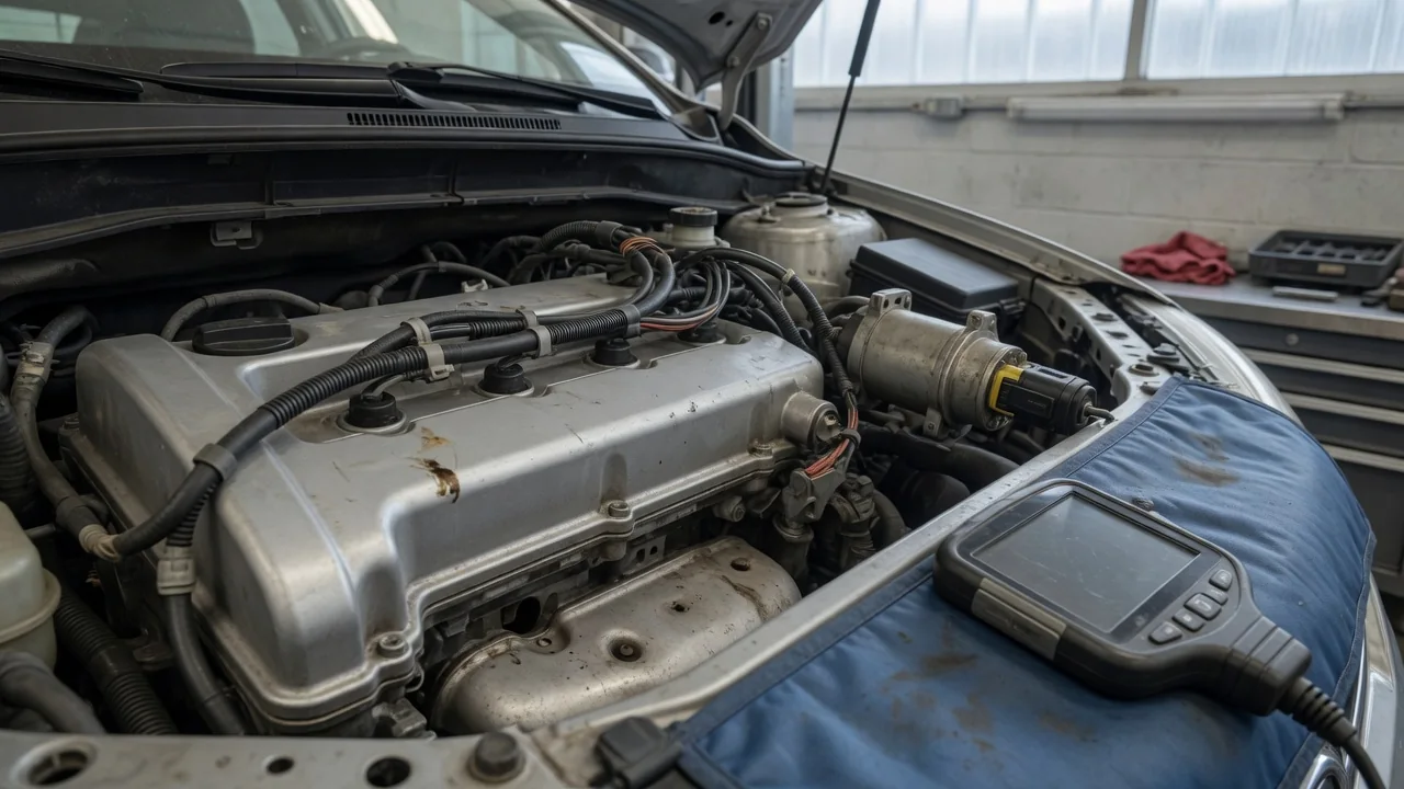
A P0026, P0027, P0028, or P0029 code points to a valve control solenoid range/performance concern on intake or exhaust, bank 1 or bank 2. These faults flag that commanded valve operation did not stay within the expected window. They do not by themselves prove a solenoid has failed. Confirm the exact definition, engine layout, oil path, and test procedure for the year, manufacturer, and engine before any parts decision.
What P0026, P0027, P0028, and P0029 Identify
The standard P0026 label is intake valve control solenoid circuit range/performance on bank 1. A P0027 code uses the matching exhaust valve control description on the same bank. Those labels are a starting point, not a universal definition. Some manufacturers apply similar wording to oil-control solenoids that move cam phasers; others use different hardware. Service information for the vehicle's year, engine, and maker must confirm the exact wording, the valve-control design, and the published diagnostic procedure before the fault is interpreted.
A P0028 code is the usual intake valve control solenoid circuit range/performance fault on bank 2. A P0029 code is the exhaust counterpart on that bank. Bank 1 is the bank that contains cylinder 1; bank 2 is the opposite bank on a V-type or opposed engine. Locating the relevant bank and solenoid requires the vehicle's service information, because numbering and placement vary by engine. A range/performance fault means the control system saw a result outside the expected window. That evidence does not, by itself, prove the solenoid has failed.
Symptoms and Signs That Require Stopping
A stored P0026 code, or a related P0027, P0028, or P0029 code, often turns on the check-engine light. Some drivers notice rough running, hesitation, or reduced power when intake valve control or exhaust valve control is not tracking as commanded. Other vehicles show little or no drivability change, especially if the control system has already limited valve timing. Those symptoms cannot identify which solenoid is involved or what failed. Bank identification, freeze-frame data, and the exact stored code are needed before any cause is assumed.
Stop safely and shut the engine off if an oil-pressure warning appears, if there is pronounced mechanical knocking, or if the engine runs so poorly that continued operation is unsafe. Those signs can point to lubrication or mechanical trouble that a range/performance fault does not fully describe. For a steady check-engine light without those urgent symptoms, arrange prompt diagnosis rather than waiting for the condition to worsen. No general driving distance is safe to promise, because oil control passages and related hardware can degrade without a new warning.
Oil Level, Oil Condition, and Recent Service Clues
Where valve timing is hydraulically operated, engine oil pressure and the oil itself are part of the control path. Low level, overfill, the wrong specification, contamination, or restricted oil control passages can keep a valve control solenoid from delivering the expected cam response. Check the level only by the owner's manual method, with the vehicle safely parked and the engine in the specified hot or cold condition. Do not judge the system from a glance at the dipstick after an unplanned shutdown.
Confirm the oil specification listed for that engine and review recent service, leaks, and when the P0026 code or companion fault first appeared. A recent oil change with the wrong product, a missed fill, or a slow leak can matter as much as a solenoid itself. Oil appearance cannot establish viscosity, internal cleanliness, or adequate pressure, so dark oil is not a diagnosis. Treating the engine with additives or a flush is not a diagnostic shortcut and can hide, rather than isolate, the true range/performance cause.
Checking the Solenoid and Its Electrical Circuit
With the engine off and cool, an owner can look at accessible wiring and connectors at the intake or exhaust valve control solenoid for obvious damage, loose connections, or oil contamination. Do not probe terminals, apply battery voltage, or handle an energized component. A technician uses the vehicle's wiring diagram and published specifications to check circuit integrity, power supply, grounds, and control operation as they apply to that design. Solenoid circuit testing belongs with those documents, not with a generic resistance chart.
Manufacturer-supported scan-tool activation can command the solenoid and compare commanded valve operation with cam or position response data. That test helps evaluate electrical and mechanical response of the valve control solenoid, but it does not prove every hydraulic passage is clear. A resistance reading within a printed range, or an audible click, also cannot confirm correct operation under oil pressure and load. If the circuit and command look normal while the range/performance condition remains, the next checks belong on the oil side and the related mechanical hardware.
How Oil Pressure and Hydraulic Operation Are Tested
Oil level and oil pressure are separate checks. A correct dipstick reading does not establish that the engine can deliver adequate operating pressure to the valve control solenoid and its oil control passages. A technician measures pressure at the manufacturer-specified test location, under the published operating conditions, with the correct gauge or transducer and the vehicle-specific limits. Those limits are not interchangeable across engines, so a universal pressure number is not a substitute for the service information.
Pressure results may send diagnosis toward oil supply, pickup or gallery restrictions, leakage, or mechanical wear, without identifying a failed part by themselves. Acceptable pressure at one test point can still leave a local valve-control oil-feed problem unresolved, which is why a P0026, P0028, or related range/performance fault can persist after a good gauge reading. Further isolation follows the vehicle's hydraulic layout rather than a generic hot-engine test routine. The measured value is evidence to interpret with the rest of the data, not a parts replacement order.
A Diagnostic Sequence That Confirms the Cause
Start by recording every stored and pending code, freeze-frame data, observed symptoms, and recent work before any diagnostic data is cleared. Capture engine temperature, load, and rpm from the freeze frame, because a P0027 code or P0029 code set during a cold idle is not the same event as one set at highway load. Vehicle-specific service information then ranks related electrical, oil-pressure, or valve-control faults and selects the next test. Clearing the memory first erases the evidence needed to choose that path.
Repair decisions should follow the test findings: oil concerns, a circuit fault, a confirmed solenoid malfunction, or a verified hydraulic or mechanical problem. Replacing a valve control solenoid because a range/performance code is present is not a diagnosis. After work, confirm the repair with the operating checks and scan data the procedure calls for, then watch for returning codes on a complete drive cycle. Turning the check-engine light off by clearing memory does not prove the original fault is gone.