Oxygen Sensor Thread Size, Tap Selection, and Thread Repair
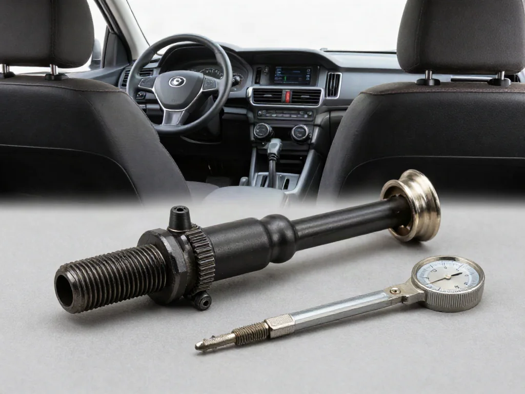
Oxygen sensor thread size is a metric specification, not a wrench size. Many sensors use an M18 × 1.5 thread, yet that common pitch still has to match the exhaust bung on the vehicle in question. When threads are dirty, deformed, or damaged, a matching oxygen sensor tap, thread chaser, insert, or bung repair kit may restore a usable path. Socket and hex dimensions are a separate subject and are not covered here.
Common Oxygen Sensor Thread Size and Pitch
A widely used oxygen sensor thread size is M18 × 1.5, which describes the sensor's external thread rather than any turning tool. In that metric designation, M18 is the nominal major diameter in millimeters, and 1.5 is the metric thread pitch, the distance in millimeters from one thread crest to the next. That pair of numbers must still be confirmed for the actual sensor and the vehicle, because other diameters or pitches can appear on some applications. Using an assumed size without checking the specified part risks a mismatch at the bung.
Those oxygen sensor threads engage the matching internal threads in the exhaust bung, so the sensor can advance until its sealing face meets the sensor seating surface. Correct engagement depends on diameter, pitch, and a clean, complete thread form on both parts. A bung that is out of round, shortened, or already damaged will not make a reliable seal even if the numbers look right. Keep these thread dimensions separate from wrench or socket sizes; those turning dimensions are outside this discussion and do not identify the thread.
Confirm the Thread Specification Before Choosing a Tool
Before selecting any oxygen sensor tap or related tool, confirm the thread specification from vehicle service information and from documentation for the correctly specified replacement sensor. That paperwork is the primary source for diameter and oxygen sensor thread pitch on that application. A thread gauge and a diameter measurement on an accessible, undamaged original sensor can support identification of what is already in the bung. Those measurements still do not prove the part is the specified sensor for the vehicle, or that a replacement with a different thread will fit.
Any tap for oxygen sensor work, and any thread chaser used on the bung, must match both the confirmed thread diameter and the pitch. Oxygen sensor tap size is not interchangeable across pitches even when the major diameter looks similar. An old sensor of uncertain origin, a previously mixed part, or a sensor with damaged threads should not be the sole reference for tool selection. Flattened or stretched crests can mislead a gauge, and a mismatched tool can enlarge or recut the bung instead of following the intended path.
When an Oxygen Sensor Thread Chaser May Help
Light carbon, scale, or minor deformation on otherwise complete oxygen sensor threads may be candidates for professional thread chasing after inspection. The goal is to restore the existing thread path so a specified sensor can start and seat without binding. Product labels may call a tool an oxygen sensor tap even when the intended function is chasing rather than cutting a new thread. Check the tool's stated purpose, thread size, and whether it is meant to follow an existing form or to remove parent metal.
Thread chasing restores an existing helix. A cutting tap removes material and can enlarge, recut, or start a different form if it is forced or misaligned. Neither action replaces missing metal, so a bung with torn or incomplete threads is not restored by chasing or tapping alone. Alignment with the original axis, enough access to keep the tool square, and control of chips and scale matter because debris left in the exhaust path can affect the sensor or nearby components. Those conditions belong in a shop setting rather than as improvised under-vehicle work.
Recognize Thread Damage and the Limits of Visual Checks
On cooled, safely accessible parts, flattened crests, torn metal, cracks in the bung, or damage around the sensor seating surface are visible reasons to stop and inspect further. Binding while starting a sensor, unexpected looseness, or a sensor that will not reach a seated position can have several causes. Incorrect diameter or pitch, cross-threading, debris, a distorted bung, or a damaged seat can produce similar feel. Those observations are clues, not a complete diagnosis of which feature failed.
Soot staining around the bung may suggest an exhaust leak at the joint, though the stain does not by itself prove the threads are the leak path. A stored diagnostic code is evidence to interpret with vehicle-specific service information; it does not establish thread damage or prove a sensor has failed. Manufacturer-dependent codes require confirmation on that vehicle. If resistance increases sharply or damage is apparent, stop rather than forcing the sensor, and do not work on hot exhaust parts. Professional inspection is the safer next step.
What Oxygen Sensor Thread Repair Inserts and Kits Do
When the original internal thread in the bung is damaged beyond chasing, oxygen sensor thread repair may use a thread insert that supplies a new internal thread inside a prepared opening. The insert becomes the mating surface for the sensor's external thread if remaining wall thickness and bung material can support it. An oxygen sensor thread repair kit is only as useful as its stated dimensions, exhaust application, and installation requirements. A Helicoil oxygen sensor thread repair kit still requires verification for exhaust heat, the confirmed thread size, and that vehicle's bung geometry.
Suitability still depends on bung material, remaining wall thickness, how far the damage extends, whether the sensor seating surface can be restored, and whether the sensing tip will have clearance after the insert is in place. Opening preparation, insert retention, and debris control need equipment and professional judgment because a poorly retained insert can loosen under heat and vibration. The finished internal thread must match the specified sensor, and the insert must stay aligned with the original bung axis. Heat cycling and exhaust vibration make retention and seating geometry as important as the thread form itself.
When Bung Repair Is Needed and How the Repair Is Checked
Cracks, severe corrosion, too little remaining material, or a damaged seating surface can put the bung beyond insert repair. In those cases the exhaust component itself may need bung or pipe repair so the sensor can sit at the intended depth and angle. A bung repair kit may contain a replacement bung that requires welding into the pipe or manifold. The kit name alone does not establish suitability for the alloy, wall thickness, or location. Professional assessment of sensor position, seating geometry, and nearby component clearance should precede that work.
After repair, checks include secure seating of the specified sensor, absence of an exhaust leak at the joint, wiring clearance away from heat and moving parts, and sensor operation against vehicle-specific service information. Clamp load and thread engagement vary by application, so torque and seating procedure come from that vehicle's service information rather than a single figure. A sensor that starts freely and seats on a restored face is a better sign than thread appearance alone. Final confirmation still belongs with the procedures published for that vehicle, including any required monitor or drive-cycle checks after the repair.