NAG1 Transmission Input Speed Sensor Identification
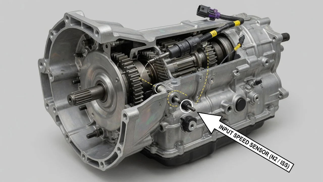
Owners chasing a speed sensor code on a NAG1 automatic often expect a single bolt-in sensor on the outside of the case. That is not how this transmission is built. This guide explains where the NAG1 input speed sensors are, what they measure, why the TCM relies on two of them, and how to approach diagnosis without assuming a part has failed just because a code or symptom points in its direction.
Where the NAG1 input speed sensors are
The NAG1 is the five-speed electronically controlled automatic that Chrysler, Dodge and Jeep used in many rear-wheel-drive and four-wheel-drive models, and it is closely related to the Mercedes-Benz 722.6 family. It does not use one external input sensor. Instead, it has two Hall-effect input speed sensors, usually referred to as N2 and N3. Both are mounted inside the transmission on the conductor plate, the plastic-and-metal assembly that sits on top of the valve body and also carries the solenoid connections and the fluid temperature sensor.
Because of that layout, the sensors are not visible from under the vehicle with the pan installed. Reaching them means draining the fluid, removing the pan and filter, and removing the valve body with the conductor plate attached. On many applications the input speed sensors are serviced as part of the conductor plate rather than as separate pieces, so identifying the correct replacement is really a matter of identifying the correct conductor plate assembly for that transmission.
How the two sensors work together
Each sensor reads a rotating member in the front portion of the gear train and sends a pulse signal to the transmission control module. The TCM uses those signals to calculate input, or turbine, speed. In some gear ranges one of the monitored members is held stationary, so a single sensor would report zero even though the input shaft is turning. Using two sensors lets the TCM choose the signal that is valid for the current gear and still know how fast the input side is spinning.
The TCM compares calculated input speed with output speed to confirm which gear is engaged, monitor clutch slip and adapt shift timing and pressure. Output speed comes from a different source than N2 and N3, and that source varies by application, so an output speed fault is a separate diagnostic path. When the TCM sees an input signal that is missing, implausible or disagrees with the expected gear ratio, it can set a diagnostic trouble code and, depending on severity, place the transmission in limp-home mode.
Typical shift behavior during that protective state includes the transmission holding one forward gear, often second, along with firm engagements and no upshifts or downshifts. These symptoms show that the TCM has lost confidence in its data. They do not by themselves prove which component caused it.
What changes the answer
Confirm the transmission type first. Not every Chrysler, Dodge or Jeep from the same era uses the NAG1; some models in the same lineup used Chrysler-designed automatics with entirely different sensor layouts, procedures and fluid specification. The model year, engine, drivetrain and build data tied to the VIN are the reliable way to establish what is installed. A dealer or a parts system that decodes the VIN can confirm it.
Fitment of conductor plates also varies. Part numbers changed across model years and applications, and gasoline, diesel, two-wheel-drive and four-wheel-drive versions are not automatically interchangeable. A plate from a donor transmission may look identical but carry different internal calibration or connector details. After a conductor plate or valve body replacement, many NAG1 applications also require a scan-tool adaptation or relearn so the TCM can learn the new hardware; skipping it can leave shift quality poor even when the new part is correct.
Diagnostic codes are another variable. Generic input speed sensor codes in the P0715 to P0717 range are commonly associated with this circuit, but the exact definitions, enabling conditions and related manufacturer-specific codes depend on the vehicle and TCM software. Read the full code list and freeze-frame data rather than reacting to one code number.
What the owner can do
Start by recording every stored and pending code with a scan tool capable of reading the transmission module, not only the engine module. Note when the fault appears: on a cold start, after the transmission warms up, over bumps or at a particular speed. Intermittent faults that change with temperature or vibration often point toward wiring or connection problems rather than a sensor that has failed outright.
Check the basics that affect every electronic signal. A weak battery, poor grounds or charging problems can produce speed sensor and solenoid codes on this transmission. Inspect the round electrical connector where the vehicle harness plugs into the transmission case. A known weakness on this family is fluid leaking past the connector seals, which can contaminate the connector and, in some cases, wick into the vehicle harness. Wet, oily pins or a fluid-soaked harness are worth documenting before anything is replaced.
Review the service history as well. Note when the fluid and filter were last serviced, whether the correct fluid specification was used, and whether the fluid level was set by the proper temperature-based procedure. Low or wrong fluid can cause slip that the TCM interprets as a ratio or speed problem. If the data and inspection still point to an internal fault, the usual repair options are replacing the conductor plate, replacing it together with related seals and the connector adapter, or having a transmission shop evaluate the valve body as a whole.
Limitations and next step
Without live data and circuit testing, nobody can confirm that N2 or N3 itself is defective. The same codes and limp-home behavior can result from connector contamination, harness damage, low system voltage, a conductor plate fault elsewhere in the assembly, TCM issues or internal mechanical problems. Replacing a conductor plate on symptoms alone can cost a significant amount without fixing the cause.
The practical next step is to confirm the exact transmission and part number from the VIN, gather the full code and freeze-frame record, and fix any voltage, connector or fluid problems first. If the fault persists, a shop with a scan tool that can display both input speed signals and perform the required adaptation is the right place to confirm the diagnosis and complete the repair. Vehicle-specific service information should govern torque values, fluid fill procedure and the relearn steps for that particular model.