LS Engine MAF Sensors: Housing Sizes, Swap Fitment, and Calibration
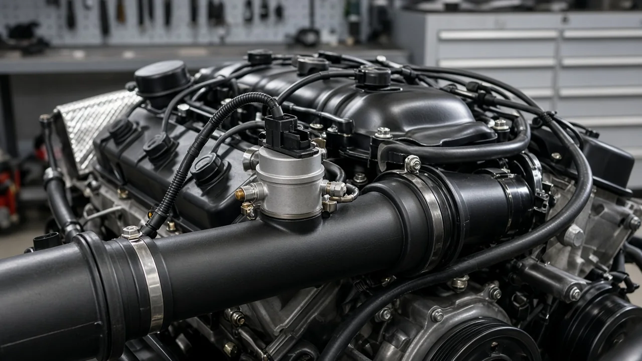
Choosing an LS mass air flow sensor is not a one-size decision. Builders working with an LS1, LS3, LS7, or another LS engine need the housing, sensor, intake layout, and controller calibration to agree before the meter can report incoming air correctly. Housing diameter, transfer function, and swap fitment all matter, and a performance or upgraded unit only helps when it solves a documented measurement or packaging problem rather than a guessed restriction.
Identify the LS Engine, Controller, and MAF Assembly
An LS mass air flow sensor does not work in isolation. Incoming air is measured as a combination of the sensing element, the housing it sits in, the intake tube geometry that shapes the flow, and the ECU calibration that converts the sensor signal into a usable air-mass value. The controller expects a particular sensor signal format and a matching MAF transfer function. Change the housing, the placement, or the controller, and the same physical meter can report a different air mass even when the engine is unchanged.
Before buying parts, collect the identifiers that actually define the assembly: engine application, controller family and calibration, sensor part number, housing details, and harness documentation. An LS engine designation alone cannot establish MAF fitment, signal compatibility, or calibration requirements, because the same family has used different housings, connectors, and transfer functions across years and vehicle platforms. Confirmed component specifications from application documents or the installed parts themselves take priority over assumptions based on appearance, a seller description, or a listing that simply says the unit fits an LS engine.
Confirm the LS1 Sensor and Housing Specifications
An LS1 mass air flow sensor still needs application-specific documentation before anyone can state housing size, connector configuration, or sensor specification. LS1 applications have used more than one housing and connector, so engine family is not a single meter. Nominal product size, connection diameter, and the internal bore at the sensing location are different measurements. A catalog may quote a clamp size that does not match the MAF housing diameter the air actually travels through. Without verified application data, treat published sizes as claims to confirm rather than values to load into a calibration.
Safe visual identification starts with the engine off and cool. Inspect the installed assembly for housing markings, connector style, and how the sensor sits in the tube, and do not touch the sensing element. MAF sensor orientation should match the component documentation, including any flow-direction marks. A replacement housing or an altered intake tract needs a calibration review even when the original sensor plugs in, because changing the bore or the path to the element changes how the meter samples air. Connector fit only proves the plug matches, not that the transfer function still applies.
Establish LS3 and LS7 Intake Measurement Requirements
Treat the LS3 mass air flow sensor and the LS7 mass air flow sensor as separate applications. Each combination of engine, intake, housing geometry, and controller has its own measurement arrangement, and those details have to be verified rather than assumed from the engine code. A sensor insert that looks familiar does not establish a complete housing diameter or the airflow measurement range the assembly can support. The insert only occupies part of the tube; the surrounding bore, screen, and intake tube geometry determine how much air can pass and how that air is presented to the element.
Any stated dimension for either family needs verified application or component documentation. Do not assign one universal diameter to LS3 or LS7 intakes, because housing styles, aftermarket tubes, and factory layouts are not interchangeable by engine name. Sensor placement, MAF sensor orientation, and local airflow conditions also affect whether the configured MAF transfer function remains valid. Disturbed flow, a bend too close to the element, or a reversed housing can make the controller's expected curve disagree with the air that actually reaches the sensor, even when the electrical connector and part number look correct.
Plan the MAF Integration for an LS Swap
An LS swap mass air flow sensor has to match more than the intake tube. Confirm that the controller supports the chosen meter, that the sensor signal format is what the ECU expects, that the harness pinout is documented, and that power and ground requirements are met. Many LS assemblies also include or rely on an intake air temperature sensor, and that circuit must be accounted for in the swap wiring. Connector fit alone does not confirm electrical or calibration compatibility. Use verified wiring documentation and qualified support before assuming a plug-and-play result.
Intake planning should keep joints secure, mount the sensor as the housing requires, and prevent unmetered air from entering downstream of the measurement point. A leak after the MAF lets air reach the engine that the controller never counted, which distorts fueling even if the sensor itself is healthy. Once the swap is assembled, the completed combination still needs professional calibration validation across the intended operating range. Idle, part throttle, and higher load all sample different portions of the airflow measurement range, so a tune that looks stable in one region can still be wrong in another.
Determine Whether a Performance MAF Addresses a Measured Limit
A performance mass air flow sensor label or a larger housing does not establish a power gain and does not prove the existing MAF is limiting airflow. The meter reports air mass; it is not a power part by itself. Before anyone recommends an upgrade mass air flow sensor, a qualified tuner needs evidence: whether the current assembly is approaching its airflow measurement range, whether the signal is saturating or becoming noisy, and whether the intake itself is the restriction. Visual size and marketing language are not substitutes for that data.
Changing housing geometry changes the relationship between sensor output and reported air mass, so the controller needs an appropriate MAF transfer function for the new assembly. A bigger bore that still uses the old curve will misreport airflow and drive fueling errors. An upgraded assembly should be recommended only when documented controller support, usable calibration data, and application suitability are in hand. Without those, the swap may plug in and still leave the ECU calibration guessing at air mass across the operating range the engine actually uses.
Validate Airflow Readings and Recognize When Testing Is Needed
An unsuitable or incorrectly calibrated setup can show up as unstable idle, hesitation, stalling, or abnormal fuel trims. Those symptoms are reasons to investigate, not proof that the MAF has failed. A fault code is evidence to interpret, not a verdict that a part is bad, and manufacturer-dependent codes still need vehicle-specific confirmation. Safe observations come first: loose connectors, damaged visible wiring, unsecured intake joints that can admit unmetered air, and mounting orientation checked against the component documentation. Do not probe or clean the sensing element as a first step.
Scan data has limits. Fuel trims and airflow readings need operating context, including temperature, load, and whether the intake is sealed, and they cannot alone identify a failed sensor. A high or low trim can come from unmetered air, a mismatched transfer function, a wiring issue, or a controller that was never calibrated for the installed housing. When symptoms persist, professional leak testing, electrical diagnosis, and calibration review are the next step. Loaded engine testing belongs with a properly equipped professional, not with improvised road experiments that can mask or create further problems.