Inside a CVT: Pulleys, Belt, Stepper Motor and Sensors Explained
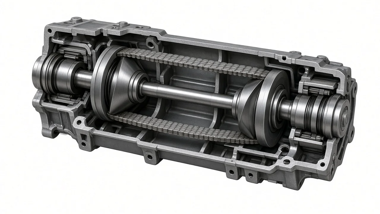
A look inside a CVT transmission shows a pulley-based drive rather than stacked fixed gears. The rotating assembly uses a primary pulley, a secondary pulley, and a steel push belt or CVT chain to vary ratio continuously. Around those parts sit hydraulic circuits, a valve body, sensors, and on some designs a stepper motor for ratio control. Layouts differ by family, so a cutaway explains relationships rather than one universal map.
A Guided Look Inside a Pulley-Based CVT
Inside a pulley-based CVT, torque does not step through a conventional gearset. Power typically enters through an input mechanism, then reaches the primary pulley on the input shaft. A belt or chain spans to the secondary pulley, and output gearing carries rotation toward the differential. That path is the core of what you see inside of a CVT transmission, though the input hardware, case shape, and final-drive arrangement still vary by design family.
The housing, shafts, and bearings hold that rotating assembly in alignment while fluid passages feed the pulley pistons and other hydraulic circuits. Looking inside a CVT transmission in a cutaway is useful because it shows how the primary and secondary pulleys sit relative to the belt, pump, and valve body. It cannot establish the exact layout of a particular vehicle. Case halves, shaft lengths, and passage routing follow the transmission design, so two pulley-based units can share a principle and still package parts differently.
How the Pulleys and Belt or Chain Change Ratio
Each CVT transmission pulley is a pair of sheaves: one sheave is typically fixed on the shaft, and the other can slide axially. As the movable sheave closes, the steel push belt or chain is forced outward and the effective running radius grows. As the sheave opens, the element rides closer to the hub and the radius shrinks. Ratio control is therefore a geometry change at the pulley faces rather than a shift from one discrete gear to another.
The primary pulley and secondary pulley move in coordination so belt wrap stays taut across a continuous range of ratios. When the primary radius increases and the secondary radius decreases, the overall ratio becomes numerically lower, supporting higher vehicle speed at a given engine speed. Torque is transmitted by a steel push belt or a CVT chain, whichever the installed design uses. Controlled clamping pressure keeps the element from slipping, while appropriate lubrication protects the sheaves and element. Those pressures are managed hydraulically; they are not owner-adjusted settings.
The Supporting Parts That Manage Engagement and Fluid Flow
An oil pump, typically driven with the input, supplies hydraulic pressure through the valve body and internal passages. The valve body meters that pressure to pulley pistons, clutches or a converter circuit, and lubrication galleries according to commands from the transmission control module. Fluid is doing three jobs at once: lubricating the belt or chain and bearings, carrying heat away from the sheaves, and acting as the working medium that moves the pulley sheaves. Without regulated pressure, ratio control and clamping both suffer.
At the input, some CVTs use a torque converter and others use a starting clutch; a given unit does not necessarily contain both. Filters or strainers protect the pump and valve body from debris, seals keep pressure in the pulley pistons and case, and cooling connections route fluid to an external cooler or heat exchanger. Those supporting CVT transmission parts are arranged to the specific transmission, so cooler line positions, pan or side-cover access, and filter style follow the case design rather than a single pattern.
What a CVT Stepper Motor Controls
Some designs use a CVT transmission stepper motor, also called a step motor, to position a hydraulic ratio-control valve in the valve body. The transmission control module commands a precise number of steps, the motor moves the valve, and hydraulic pressure to the primary and secondary pulley circuits changes. Pulley sheaves then open or close until the commanded ratio is reached. In that architecture, the stepper motor is an electromechanical link between electronic ratio requests and hydraulic actuation, not a device that physically turns the pulleys.
A stepper motor CVT transmission is not the only control method. Other families use solenoid valves, linear solenoids, or different actuators for ratio control, so the presence of a step motor must be confirmed by transmission type rather than assumed from symptoms. Poor ratio response or unusual engine-speed behavior can come from fluid condition, pump output, pulley hydraulic leaks, sensor data, or wiring as readily as from the motor itself. Those signs are reasons to diagnose the control loop, not proof that the stepper motor has failed.
How CVT Sensors Report Speed, Temperature and Pressure
CVT transmission sensors give the control module a running picture of shaft speed, fluid condition, and, where fitted, hydraulic pressure. An input speed sensor typically reports rotation at the primary pulley or input shaft, while an output speed sensor reports the secondary pulley or output shaft. Comparing those speeds lets the module verify the actual ratio against the commanded ratio. A mismatch can indicate slip, a hydraulic delay, or a signal problem, but the reading is evidence to interpret, not a verdict that a pulley or belt has failed.
A fluid temperature sensor helps the module decide when to allow full hydraulic pressure, when to modify ratio strategy, and when to protect the unit from overheating. Pressure sensors, when the design includes them, close the loop on clamping and ratio circuits. Mounting varies: a sensor may thread through the case, sit inside an internal assembly, or share a connector with other electronics. A sensor-related fault can involve wiring, connectors, the tone wheel or other signal target, or operating conditions such as low fluid level, so professional testing is needed to identify the cause.
Finding the Correct Speed Sensor Location on a Nissan CVT
Nissan CVT transmission speed sensor location is not a single point on every case. Before anyone can specify which connector or boss is the input, output, primary, or secondary sensor, the vehicle model, model year, engine, and transmission identifier must be known. Those names also have to be checked against the applicable service diagram, because a primary speed sensor on one family may sit at a pulley, while another unit labels the same function as an input speed sensor and mounts it elsewhere.
Presenting one Nissan location as universal would mislead, so a verified example is used only when that transmission's sensor position and mounting are confirmed for that identifier. An owner can record symptoms and, with the vehicle parked and switched off, note any safely visible external connectors on the case. Underbody access, disassembly, and electrical testing belong with a qualified technician. Scan data and circuit tests then help separate a sensor signal problem from an internal issue such as pulley hydraulic delay, because a manufacturer-dependent code still needs vehicle-specific confirmation.