How to Build Adjustable Control Arms: A Practical DIY Guide
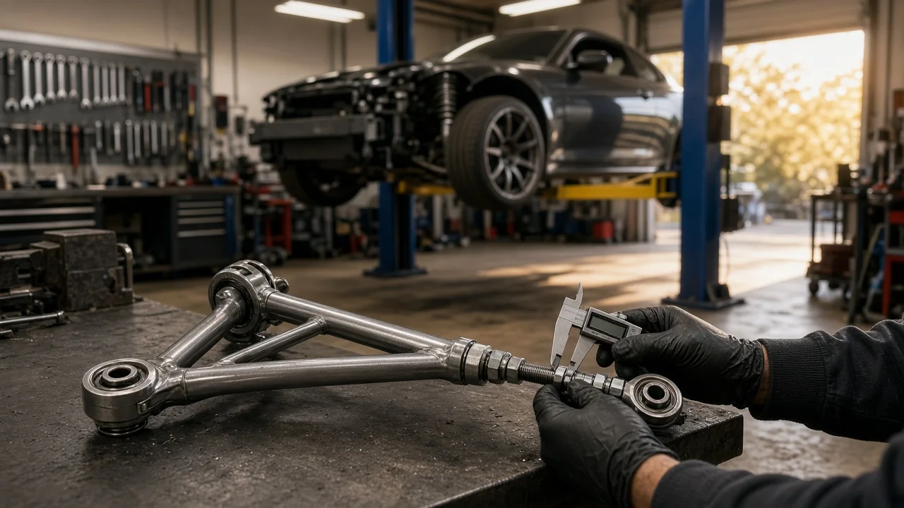
Adjustable control arms let you correct suspension geometry after a lift, a drop or worn mounting points. Many owners wonder whether they can make their own instead of buying a finished set. The honest answer depends on your suspension design, your fabrication skill and how the vehicle will be used. This guide explains how adjustable arms work, what a realistic DIY build involves, which situations call for caution and when you need vehicle-specific data or a professional shop.
The Short Answer
For most owners who want to build their own adjustable control arms, the job means assembling engineered components rather than fabricating an arm from raw steel. A typical DIY arm uses a threaded tube or arm body, a right-hand and a left-hand threaded end, jam nuts, and bushings or rod ends chosen for the vehicle. Kits and weld-in threaded bungs make this practical on solid-axle trucks, SUVs and off-road builds, where links are simple straight members. Fabricating a complete arm from scratch is a different job. It requires proper tubing, accurate jigging, structural welding and an understanding of load paths. Control arms carry braking, acceleration and cornering forces, so a failed weld or joint can let a wheel move unexpectedly and cause loss of control.
If you are not an experienced fabricator, the safer option is a commercially engineered arm designed for your vehicle, or a kit with matched components. Home-built arms suit experienced builders, off-road projects and dedicated competition vehicles. Even then, local inspection or road-use rules may apply.
How Adjustable Control Arms Work
A control arm locates the wheel or axle relative to the body or frame. With fixed-length arms, the arm length and its mounting points set the factory geometry. An adjustable arm changes its effective length, usually through a turnbuckle-style adjuster. One end threads in with a right-hand thread and the other with a left-hand thread, so rotating the body lengthens or shortens the arm without disconnecting it. Jam nuts then lock the ends so the setting cannot drift.
What the length change does depends on where the arm sits. On an independent front suspension, changing the length or position of the upper arm mainly alters camber and sometimes caster. On a solid-axle link suspension, adjusting the upper or lower trailing links changes caster at the front or pinion angle at the rear. An adjustable track bar re-centers the axle side to side after a ride height change. The joints matter as much as the adjuster. Rubber bushings isolate noise and vibration, and polyurethane is firmer. Rod ends or articulating joints allow more travel but transmit more noise and need regular inspection for joint play.
What Changes the Answer
Suspension type is the biggest factor. Straight links on a three-link or four-link solid axle are the most DIY-friendly because they are loaded mostly in tension and compression. Upper and lower A-arms on independent suspensions are a different case. They are shaped parts that carry ball joints and see bending loads, and in some designs they also mount springs or shocks. Copying them accurately at home is much harder. Lower arms that support a spring, and arms on strut-type suspensions, are generally poor candidates for home fabrication.
Intended use also changes the answer. A daily driver needs quiet, durable bushings and parts that can pass inspection. A rock crawler may accept noise in exchange for articulation. The amount of lift or lowering affects how much adjustment range you need, and very large changes in ride height may require relocated brackets rather than longer arms. Material, tube wall thickness, rod end size and thread engagement all have to suit the vehicle's weight and loads. Those figures come from component manufacturers or the vehicle's engineering data, not from guesswork.
Measuring and Choosing Components
Start with the factory service information for your vehicle, including arm locations, mounting hardware and the fastener specification. Measure each stock arm from the center of one mounting eye to the center of the other, with the suspension at its normal ride height. Record each arm separately, because left and right lengths are not always identical. At each mounting point, note the bushing sleeve width and bolt diameter so the new ends fit the brackets without spacers or slop.
Choose components rated for the application. Threaded ends, rod ends and bungs should come from a manufacturer that publishes load ratings and minimum thread engagement for its parts. If you weld bungs into tubing, use tubing suited to structural use and keep the bungs aligned on a common axis. Have the welds done by someone qualified for load-bearing work. Plan the adjustment range so that both ends reach the target length with full thread engagement. An arm that only reaches its length by hanging onto a few threads is unsafe.
Installing and Setting the Arms
Proper vehicle support comes first. Lift only at the manufacturer's recommended points, place rated jack stands on firm level ground and chock the wheels that stay down. Never work under a vehicle held only by a jack. Support the axle or arm with a jack before removing any fastener, because springs can push or drop components suddenly. Arms that hold a coil spring may require a spring compressor; handle them with extreme caution or leave that job to a shop.
On a link suspension, replace one arm at a time so the axle stays located. Set each new arm to the measured stock length before installing it, which keeps the vehicle drivable to an alignment shop. Apply thread lubricant or anti-seize only if the part manufacturer calls for it, since it can change clamping force. Tighten bushing bolts with the suspension at ride height rather than hanging, so rubber bushings are not clamped in a twisted position. Torque every fastener to the vehicle or component specification. Once all arms are in, center the adjusters evenly, tighten the jam nuts and book a professional wheel alignment.
Checks After the Build
After the first short drive, re-check every fastener and jam nut. Painted witness marks make it easy to see whether anything has shifted. To check for joint play, have a helper rock the wheel or steering while you watch each rod end and bushing. Listen for new clunks over bumps. Confirm that tires, brake lines and sensor wires clear the arms through full suspension travel and full steering lock. Rod ends and adjusters wear faster than sealed factory joints, so repeat these checks at regular service intervals and more often after off-road use.
Limitations and Next Step
This guide cannot give torque values, arm lengths or alignment settings, because those depend on the specific vehicle, suspension design and components. Use the factory service manual and the component maker's instructions for those figures. Have a qualified fabricator or suspension shop review the design or do the work if the build involves structural welding, ball joint housings, spring-loaded arms or a vehicle used on public roads. As a next step, identify exactly which arms on your vehicle need adjustment and why. Then choose between a proven bolt-in product, a matched kit or a fully fabricated arm based on your skills and how the vehicle will be used.