How Does an EV Stop a Charging Session? Software, Contactors and Connector Release
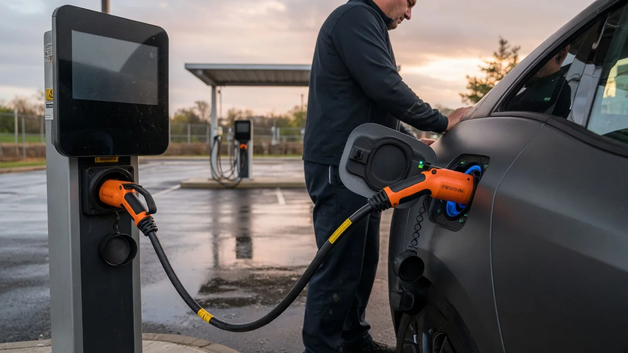
Ending a charge looks simple from the outside: the percentage stops climbing and the cable comes free. Behind that moment, an EV charging session stop follows an ordered sequence. The vehicle and the charging equipment first agree in software that energy flow should end, then reduce current, open high-voltage contactors and only afterward release the connector lock. Knowing how an EV stops a charging session explains why the steps happen in that order and why the cable sometimes stays locked for a moment.
The software command that starts the shutdown
Every orderly stop begins as a software decision. The battery management system may report that the target state of charge has been reached. A charging schedule may expire, the driver may press stop on the dashboard or in a companion app, or the station may end the session because of a payment authorization, time limit or operator command. Faults are another source: abnormal temperatures, an insulation warning, an out-of-range voltage or a lost communication link all lead to a stop request. Whatever the origin, the request does not cut power instantly. It starts a coordinated sequence in which current is reduced before any switching hardware moves.
In AC charging, coordination runs mainly over the control pilot, a low-voltage signal line defined by standards such as SAE J1772 and IEC 61851. The station uses a pulse-width-modulated pilot signal to advertise how much current the vehicle may draw, and the vehicle answers by changing the pilot voltage through a resistor network. To end the session, the vehicle commands its onboard charger to ramp its draw down, then switches the pilot from the ready-to-charge state back to the connected-but-not-charging state. The station reads that change as the instruction to de-energize the outlet. The station can also start the process from its side by changing or removing the pilot signal.
DC fast charging relies on richer digital communication because the charger, not the car, performs the power conversion. Depending on the connector system, messages travel over power-line communication on the pilot wire, as with CCS using DIN SPEC 70121 or ISO 15118, or over a CAN bus, as with CHAdeMO. When the vehicle wants to stop, it sends a request indicating that power delivery should end. The charger ramps its output current toward zero and reports back, and only then does the sequence move to the hardware stage. Message details and timing vary by protocol version and implementation, so individual vehicles and stations may behave slightly differently.
Contactors: opening the high-voltage path safely
Contactors are heavy-duty, electrically controlled switches that connect or isolate a high-voltage circuit. An EV battery pack has its own main contactors, charging equipment has contactors or relays at its output, and vehicles that accept DC charging often use dedicated contactors for the inlet path. Opening a contactor under heavy load draws an arc between the contacts that erodes their surfaces and, in severe cases, can weld them together. That is why the software stage drives current close to zero first. Switching a circuit that carries little or no current is far gentler on the hardware and supports a longer service life.
In an AC session, the switching that ends power delivery happens mostly in the station: once the pilot state changes, it opens its relay or contactor and the outlet pins go dead. Because the onboard charger has already stopped drawing power, the station is effectively switching an idle circuit. In a DC session both sides usually take part. The charger stops its output, voltage on the cable is allowed or actively made to fall, and the vehicle opens its charging contactors. Many DC systems also run a welding check, monitoring voltage on the isolated side to confirm the contacts actually separated. If a contact appears stuck, the system flags a fault instead of treating the session as cleanly ended.
Fault conditions can compress this sequence. If communication is lost, the pilot signal disappears or an isolation problem is detected, equipment is designed to open contactors promptly rather than wait for a gradual ramp-down. Standards define how equipment must react, but exact response times and recovery behavior depend on the specific hardware and software.
Connector release and the inlet lock
The final step is freeing the plug. Most charge inlets have an electrically operated lock, typically a small actuator that drives a pin or bar to hold the connector in place. Its purpose is safety: separating contacts that still carry current would arc at the pins. For DC charging, the lock normally stays engaged until current has stopped, the contactors have opened and the voltage at the inlet has dropped to a safe level. Stations with their own sockets, common with Type 2 equipment, use a similar lock on the station side to hold the cable.
How release is triggered depends on connector design and vehicle settings. On many vehicles, unlocking the doors with the key fob or pressing a button near the inlet asks the car to end the session and free the connector. On connectors with a mechanical latch, such as the J1772 handle, pressing the latch button also changes the resistance on the proximity circuit. A vehicle can treat that change as a sign the user is about to unplug and stop drawing current before the plug moves. Some vehicles let the owner choose when the cable stays locked during AC charging, which is one reason behavior differs between cars.
Practical implications and limits
The ordered sequence explains several everyday experiences. A short delay between pressing stop and being able to remove the cable is normal while the hardware steps complete. Stopping from the vehicle or from the station should end the session equally well, since either side can start the shutdown. If the plug refuses to release, common reasons are that the session has not actually ended, the vehicle is still locked, or the lock actuator is stuck, for example by ice in cold weather. Many owner's manuals describe a manual inlet release for such cases, but its location and use are vehicle-specific.
Forcing a connector is a poor substitute for the normal process. Repeatedly yanking a plug puts mechanical stress on latches, pins and the inlet, and on locked DC connectors it risks damaging the lock or the cable. Waiting for the release, or using the station's stop function, keeps wear low. Drivers should also remember that a paused charge is not always an ended session: some vehicles pause and resume within the same session, for example during scheduled or temperature-managed charging, while keeping the connector locked. Station displays and billing records may also lag behind what the dashboard shows. Exact timings, lock options and fault messages differ by vehicle, charger and protocol, so the documentation for a particular car or network remains the reference for its specific behavior.