How Does a Wheel-Speed Sensor Detect Rotation?
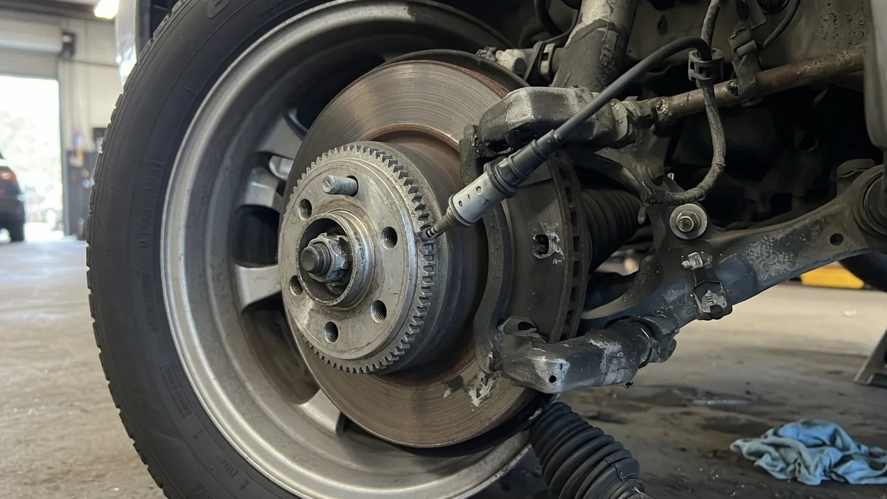
A wheel-speed sensor turns wheel rotation into an electrical signal that the vehicle's control modules can count. It never touches anything that spins. Its tip sits close to a toothed or magnetized ring, and each tooth or pole that passes changes a magnetic field. To see how a wheel speed sensor detects rotation, it helps to look at three things: how the signal is created, what its pulse frequency means, and how the anti-lock braking system uses it.
Tone ring
The tone ring, also called a reluctor or exciter ring, is the part that rotates with the wheel. Depending on the design, it may be pressed onto a CV joint housing, built into the hub or wheel bearing, mounted on an axle shaft, or machined into a brake rotor. The sensor itself bolts to a stationary part such as the steering knuckle or axle housing. It is positioned so a small air gap separates its tip from the ring. A traditional tone ring is made of ferrous metal, with evenly spaced teeth separated by gaps or slots.
In a passive sensor, often called a variable-reluctance or inductive sensor, a permanent magnet sits inside a coil of fine wire. When a tooth moves toward the sensor tip, the magnetic path becomes easier to complete and the magnetic flux through the coil increases. When a gap passes, the flux drops. This changing flux induces a voltage in the coil, so the sensor produces an alternating signal that rises and falls with each tooth. A passive sensor generates its own signal and needs no external power, which is why it typically uses a simple two-wire connection.
An active sensor works differently. It uses a Hall-effect or magnetoresistive element, and the control module supplies it with power. Some active sensors read steel teeth with the help of a built-in bias magnet. Many others read a magnetic encoder ring, which has alternating north and south poles embedded in it and is often integrated into a wheel bearing seal. Because of this, the ring may look like a plain black band with no visible teeth. The sensing element switches state each time the field changes direction, which produces a clean, digital-style signal.
Pulse frequency
Each tooth, or each pair of magnetic poles, produces one signal cycle as it passes the sensor. The frequency of the wheel speed sensor signal is therefore proportional to how fast the wheel turns, multiplied by the number of teeth or pole pairs on the ring. As a purely hypothetical example, a ring with 48 teeth turning ten times per second would produce 480 pulses per second. The control module is programmed with the correct ring count for the vehicle. It converts pulse frequency into wheel revolutions, then into an estimated road speed based on the expected rolling circumference of the tire.
With a passive sensor, both the frequency and the amplitude of the signal rise as the wheel speeds up. At very low speeds, the induced voltage can be too small to read reliably, so passive systems have a minimum speed below which they cannot report accurate wheel speed. Amplitude also depends on the air gap: a larger gap produces a weaker signal. For this reason, the module generally looks for the moments when the signal crosses a threshold rather than relying on how large the voltage is.
An active sensor outputs pulses of roughly constant amplitude, either as a square-wave voltage or as a current that steps between two levels. Frequency still tracks wheel speed, but the signal stays usable down to nearly a standstill. Some active sensor designs can also encode extra information in the pulse pattern, such as direction of rotation or signal-quality status. Whether a particular vehicle uses these features depends on its system design.
ABS use
The ABS control module reads every wheel-speed sensor continuously. From these readings it estimates a reference speed for the whole vehicle. During braking, the module compares each wheel against that reference. If one wheel slows much faster than the others, or faster than the vehicle could plausibly decelerate, the module treats it as a sign that the tire is about to lock. The difference between a wheel's speed and the reference speed is called slip, and keeping slip within a useful range is the core task of the system.
When the module detects excessive slip, it commands the hydraulic modulator to hold, release, and reapply brake pressure at the affected wheel. This cycle repeats rapidly, keeping the tire near its point of best grip while still letting the driver steer. How quickly the module can react depends partly on how often fresh pulses arrive. This is one reason the ring's resolution and a clean, uninterrupted signal matter.
The same signal is often shared with other systems. Traction control uses it to detect wheel spin under acceleration, and stability control uses it along with steering and yaw inputs. On many vehicles, the wheel speed data also feeds the speedometer, odometer, indirect tire-pressure monitoring, transmission logic, or driver-assistance functions. Exactly which systems depend on it varies by vehicle, so the service information for a specific model is the reliable reference.
Practical implications and limits
Detection depends on a clean magnetic interaction, so the physical condition of the parts matters. A cracked or corroded ring, a missing tooth, rust swelling under a pressed-on ring, metallic debris stuck to the sensor tip, or an air gap changed by bearing wear or poor seating can all distort or interrupt the pulses. Typical symptoms include ABS, traction control, or stability warning lights, and unexpected ABS activation at low speeds. On vehicles that use the signal for speed display, the speedometer may also behave erratically. Stored fault codes often describe a circuit problem or an implausible signal. They usually do not identify whether the sensor, wiring, ring, or bearing is the actual cause.
The right testing approach depends on the sensor type. For a passive sensor, checking coil resistance and watching the AC voltage while spinning the wheel can give basic information. An active sensor usually cannot be judged by a resistance reading, and it produces no meaningful output unless it is powered. In both cases, comparing all wheel speeds in scan tool live data, or viewing the waveform on an oscilloscope, tends to reveal more. A regular dropout in the waveform, for example, can point to a damaged tooth or encoder section. Magnetic encoder rings need careful handling: they can be damaged by contact with strong magnets, and on some designs they only work when installed with the correct side facing the sensor.
The sensor measures rotation, not true road speed. Mismatched tire sizes, or noticeably different tread wear between wheels, can make healthy sensors report different speeds. Depending on the system, that may set a fault or affect how the brakes and traction systems respond. Values such as air gap, coil resistance, ring tooth count, and expected waveform levels are vehicle-specific. Use the service information for the exact vehicle rather than general figures when diagnosing or replacing components.