How Does a Mechanical Speedometer Work?
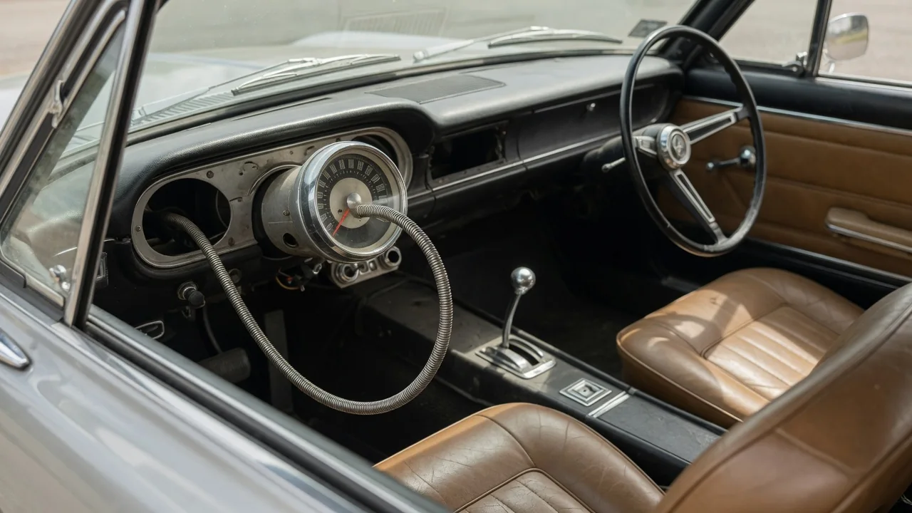
A mechanical speedometer turns the rotation of the drivetrain into a needle position without any electronics. On many older cars and trucks, a small gear set at the transmission spins a flexible cable, and that cable drives a magnetic mechanism behind the dashboard. Knowing how a mechanical speedometer works makes it easier to understand symptoms such as a bouncing needle or a stalled odometer. This guide follows the path from the drive gear, through the cable, to the gauge itself.
Drive Gear: Where the Speed Signal Starts
The speed signal begins at a shaft that turns at a rate tied to road speed. In a typical rear-wheel-drive layout, that is the transmission output shaft, or the transfer case on many four-wheel-drive vehicles. Front-wheel-drive transaxles usually take the drive from a point near the differential, and some designs, particularly on motorcycles, take it from a wheel hub instead. In the common transmission arrangement, a worm-style drive gear on the output shaft meshes with a small driven gear set at an angle to it. The driven gear rides in a housing that fits into the transmission case, and the speedometer cable connects to the outer end of that housing. Every turn of the output shaft therefore produces a fixed fraction of a turn at the cable.
The tooth counts of this gear pair are what calibrate the system. The gauge is built to show a given speed at a specific number of cable revolutions per mile, a figure that is sometimes marked on the gauge or listed in service data. The gear ratio has to deliver that number for the vehicle's axle ratio and tire size. If an owner fits noticeably taller or shorter tires, or changes the final drive gearing, the original gears no longer match, and the speedometer reads high or low. For this reason, driven gears were often supplied in a range of tooth counts, with identification methods that vary by manufacturer. Driven gears are frequently made of plastic, so they can wear or strip, especially if the cable above them binds.
Cable: Carrying Rotation to the Dashboard
In a cable drive car speedometer, the cable is a rotating shaft that can bend. Its inner core is made of tightly wound layers of steel wire, which lets it flex around corners while still resisting twist along its length. The core spins inside a stationary outer housing that guides and protects it. Each end of the core is shaped, often square, so it keys into the driven gear at the bottom and the gauge input at the top. Threaded collars or snap-in fittings hold the outer housing to the transmission and to the back of the instrument cluster, so only the core turns.
Because the core rotates in direct proportion to vehicle speed, any friction or slack along its route shows up at the needle. Gentle bends and secure mounting clips let the core spin smoothly. Tight bends, kinks or a dry, worn core increase drag, and the core can wind up slightly and then release, which makes the needle flutter or jump. On some vehicles, additional components such as a cruise control sensor or a ratio adapter are installed in the cable path, splitting it into sections. Whatever the routing, the cable carries only rotation; it does not measure anything by itself.
Gauge: Turning Rotation Into a Needle Reading
Most mechanical speedometer heads use an eddy-current, or magnetic drag, mechanism. The cable turns a small shaft carrying a permanent magnet. Close to the magnet, but not touching it, sits a cup or drum made of a nonmagnetic conductive metal such as aluminum, mounted on its own spindle with the needle attached. When the magnet spins, its moving field induces circulating electrical currents, called eddy currents, in the cup. Those currents create their own magnetic field, which interacts with the magnet and pulls the cup in the direction of rotation. A stationary steel shield around the assembly helps concentrate the field where it is needed.
The cup does not spin freely. A fine spiral hairspring attached to its spindle resists the magnetic pull, so the cup rotates only until the spring force balances the drag. Since the drag rises as the magnet spins faster, a higher vehicle speed moves the needle further around the dial, and the needle settles at a steady position for a steady speed. There is no physical contact between the magnet and the cup, which is why the needle can move smoothly and return toward zero when the vehicle slows. The precise calibration of magnet strength and spring tension is set when the gauge is built or rebuilt.
The odometer shares the same input shaft but works differently. A worm on the shaft drives a reduction gear train that slowly turns a row of numbered drums. When one drum completes a full turn, a small carry mechanism advances the next drum by one digit, so the reading builds up like a counter. Many gauges also include a resettable trip odometer driven from the same gear train. The odometer simply counts cable revolutions, while the speedometer needle reflects how fast those revolutions are happening.
Practical Implications and Limits
Because the speedometer and odometer share one input, their behavior together is a useful diagnostic clue. If both stop working at once, the fault is usually upstream of the gauge, such as a broken cable core, a disconnected fitting or a stripped driven gear. If the odometer keeps counting while the needle stays at zero or behaves erratically, the problem is more likely inside the gauge head. A needle that works while the odometer stalls points toward the odometer gear train. Squealing or ticking that changes with road speed often comes from a dry or poorly routed cable, though worn bushings in the gauge can make similar noises.
Accuracy depends on everything between the road and the needle. Tire wear, tire pressure and replacement tire sizes change how far the vehicle travels per wheel revolution, so some reading error is normal even on a healthy system. Correcting a significant error after a tire or axle change usually means selecting a different driven gear or installing a ratio adapter, using the correct figures for that specific vehicle. When servicing a cable, lubricant should be applied sparingly and kept away from the gauge end, because it can migrate into the head and affect the mechanism. Removal steps, gear identification and lubricant choices differ between vehicles, so the relevant service manual is the right reference.
Mechanical systems also have inherent limits. Gears, cable cores and gauge bushings wear with use, and the analog mechanism cannot share speed information with other vehicle systems unless an additional sensor is added. Repairing or recalibrating the eddy-current head itself typically requires specialized tools and is often handled by instrument repair shops. Still, the design is simple enough that most faults can be traced logically by following the rotation from the transmission to the dashboard.