How Do Engineers Measure Suspension Travel? Reference Points, Compression and Droop
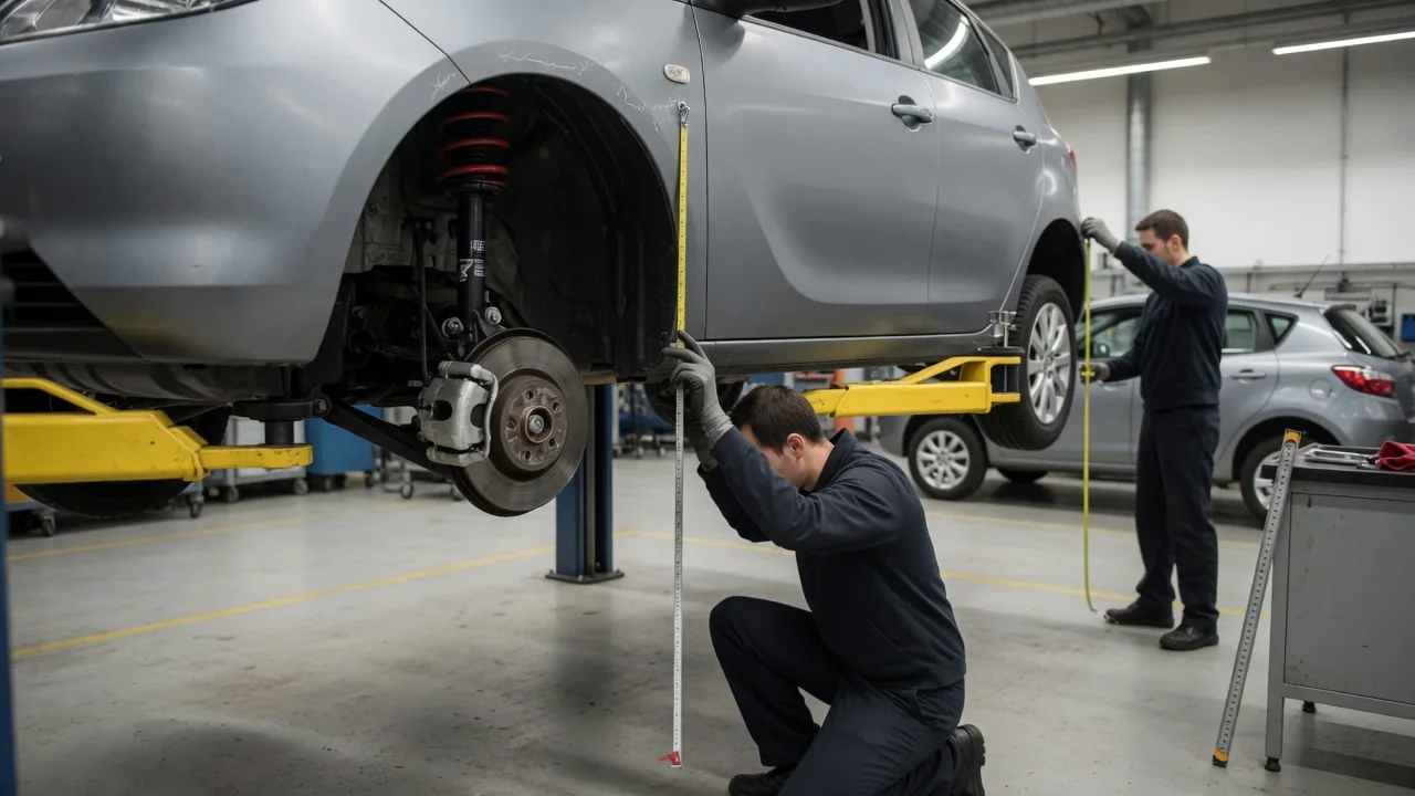
Suspension travel sounds like a single number, but measuring it properly depends on careful definitions. Engineers have to decide what the wheel moves relative to, where the movement starts, what counts as the end of the range, and how the vehicle is loaded during the measurement. This guide explains how engineers measure suspension travel. It covers the reference points they rely on, how compression and droop are separated, and why test conditions matter as much as the measuring tool.
Reference points
In vehicle dynamics work, suspension travel usually means wheel travel: the vertical movement of the wheel center relative to the vehicle body, or sprung mass. It does not mean movement relative to the road. Engineers measure travel from a defined starting position, commonly called design position, nominal ride height or trim height. That position corresponds to a specified load condition. From there, travel is stated in two directions: upward toward the body and downward away from it. Total travel is the sum of the two. Without a stated reference position, a single travel figure is ambiguous, because the same suspension can show very different upward and downward ranges depending on where the measurement begins.
Wheel travel is also different from shock absorber travel. The damper and spring are usually mounted inboard of the wheel on a control arm or axle. Because of this, they move a different distance than the wheel center does. The relationship between the two is called the motion ratio or installation ratio, and in many suspension designs it changes through the range of movement. Engineers therefore record which quantity they are reporting. They may measure damper length change from eye to eye, then convert it to wheel travel using the known geometry. Or they may track the wheel center directly.
Outside the lab, a common practical reference is the vertical distance from the wheel center to the fender lip or another fixed body point. Service procedures often specify particular chassis or body points for ride-height checks. Using the same points every time matters. Body pitch and roll, uneven floors and tire deflection can all shift a reading if the reference is not consistent.
Compression and droop
Compression, also called bump or jounce, is the wheel moving upward toward the body. Its limit is typically set by a bump stop or jounce bumper, by the damper reaching its shortest length, or by parts coming into contact. Engineers have to define where compression travel ends. Many bump stops are made of compliant material that progressively stiffens as it compresses. So there is a difference between first contact with the bump stop and the point where it is fully compressed. Some measurements report travel to first contact, others to the hard limit, and the difference can be significant for interpreting ride and handling behavior.
Droop, also called rebound or extension, is the wheel moving downward away from the body, as when a wheel drops into a hole or the body lifts. The damper reaching full extension usually limits droop. Some designs use limiting straps or rebound stops instead. Other components can impose practical limits before the hardware stops are reached, including joint angles in drive shafts, brake hose length, sensor wiring and, on some designs, the spring becoming unseated. Engineers check these clearances across the whole range, not just at the endpoints.
The split between compression and droop from the reference position is often more informative than total travel. Two suspensions with equal total travel can behave very differently if one has most of its range in compression and the other in droop. That is why travel is normally reported as separate bump and rebound values alongside the total.
Test conditions
The vehicle's load state directly changes the starting position, so engineers specify it before measuring. Typical conditions include curb weight, a defined design load with occupants and cargo, and maximum permitted load. Fuel level, tire pressure and tire size also affect ride height and are recorded or set to specification. Before a static reading, the suspension is usually settled by rolling the vehicle or cycling it up and down. This reduces the effect of friction and bushing hysteresis, which can otherwise leave the suspension resting at slightly different heights after each disturbance.
For full-range kinematic measurement, engineers often remove the spring or use a test rig that moves each wheel through its travel under control. Kinematics and compliance rigs move the wheels vertically and measure wheel position along with alignment changes such as camber and toe at each point. In simpler setups, the spring is removed and the wheel or control arm is raised in steps with a jack. Positions are then recorded with displacement gauges or careful manual measurement. Removing the spring lets the suspension reach its true mechanical limits without fighting a large preload.
Dynamic travel is measured on the moving vehicle. Linear or string potentiometers mounted across the damper, or dedicated ride-height sensors, record displacement while a data logger captures it during driving. This shows how much of the available travel is actually used on a given road or maneuver, which a static measurement cannot reveal. Articulation tests, in which one wheel is driven up a ramp or obstacle, show how far the suspension can flex before a wheel lifts or a limit is reached.
Practical implications and limits
For owners comparing figures, the main lesson is that travel numbers are only comparable when their definitions match. A value quoted as wheel travel is not interchangeable with damper stroke. A figure measured to first bump-stop contact will differ from one measured to the hard limit. Measurements taken at curb weight will not match those taken under design load. When a manufacturer's service information specifies ride-height procedures and reference points for a particular vehicle, those instructions take precedence over generic methods.
Modifications change the balance between compression and droop even when total travel looks unchanged. Lowering the body on shorter springs typically moves the resting position closer to the bump stops. That leaves less compression travel unless other parts are changed too. Raising ride height tends to shift the range toward droop and can bring joint angles or hose lengths closer to their limits. Checking clearances through the full range after such changes is more meaningful than measuring at rest alone.
Every method has limits. Fender-based measurements include body movement and tire deflection. Static measurements miss how dampers and bushings behave at speed. Compliance in bushings and the body structure can let a wheel move slightly differently under load than pure geometry predicts. Engineers treat suspension travel as a set of related measurements, each tied to a stated reference, endpoint and condition, rather than one universal number.