How Do Engineers Calibrate a Vehicle Sensor?
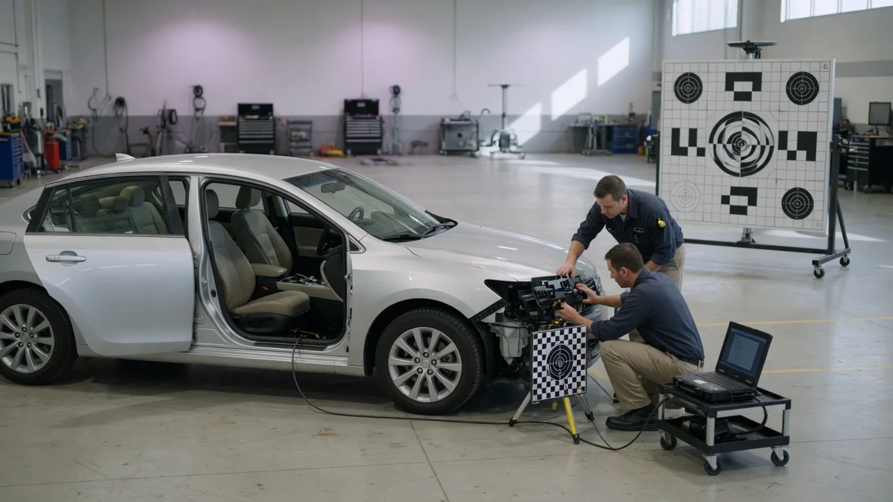
Calibrating a vehicle sensor means teaching the measurement system what its raw signal actually represents. A sensor might report pressure, temperature, steering angle or the position of a lane line. In each case, engineers follow the same logic. They expose the sensor to a known reference condition, store the resulting correction as a software value, and then check that the corrected output matches reality. These three stages are the basics of vehicle sensor calibration, and each one matters to owners.
Reference condition
Every calibration starts with a condition whose true value is already known. For a pressure sensor, that can be a set of pressures produced by equipment that has itself been checked against a more accurate standard. For a temperature sensor, it may be a controlled fluid bath or chamber held at stable points. For a steering angle sensor, the reference is often mechanical: the wheels pointed straight ahead on a properly aligned vehicle. Engineers record the sensor's raw output under that condition and later compare it with the known value.
Camera and radar sensors used in driver assistance systems need a more elaborate reference. Procedures vary by manufacturer. A static calibration places target boards at defined distances and heights relative to the vehicle's centerline or thrust line. A dynamic calibration has the system learn from lane markings and other road features during a prescribed drive. Both kinds usually assume a specific vehicle state, such as correct tire pressures, a level floor, an unloaded cabin and a completed wheel alignment. Any deviation from that state shifts the geometry the sensor is measuring.
The reference condition also limits what calibration can correct. Engineers typically record outputs at several points across the operating range, because a sensor can read correctly at one end and drift at the other. During development they may also characterize how a sensor behaves across temperature, supply voltage and aging, so the corrections cover more than a single snapshot. If the reference itself is wrong, every value derived from it will be wrong in the same direction.
Software value
Raw sensor signals are rarely usable as they come. A pressure sensor produces a voltage, a wheel speed sensor produces a pulse frequency, and a camera produces an image in pixel coordinates. Software converts these signals into engineering units using a transfer function. In its simplest form, that function is an offset and a gain. The offset shifts the reading so that zero input reads zero. The gain scales the slope so that the full range reads correctly. More complex sensors use lookup tables or polynomial corrections to straighten out nonlinear behavior.
Where these values are stored depends on the design. Some sensors carry their own calibration, programmed into internal memory during manufacturing, and send already corrected data to the control module over a digital connection. Simpler analog sensors rely on correction values stored in the calibration data of the engine or chassis control unit. Driver assistance sensors typically store learned mounting angles, such as a camera's pitch, yaw and roll offsets. Software uses these angles to compensate for small differences between the ideal position and the actual installation.
Stored values are usually bounded. Control software commonly checks that a newly learned offset falls inside an allowed window before accepting it. If the offset is outside that window, the software refuses or flags the calibration. The limit is deliberate. A value far outside the expected range more often points to a bent bracket, a wrong part or a faulty sensor than to normal manufacturing tolerances, and accepting it would hide the real problem. The word calibration is also used more broadly for the full set of tuning maps in a control unit. For an individual sensor, though, it means these correction values.
Verification
Writing a value is not the same as proving that it works. Verification compares the corrected output with an independent reference, ideally one that was not used to calculate the correction. In development, this can mean checking at points between the original calibration points to confirm that the correction holds across the range. On a vehicle, a technician may compare live data with a known condition. Examples include a steering angle reading near zero with the wheels straight, or a manifold pressure reading that matches barometric pressure with the key on and the engine off, where the procedure allows.
Cross-checks between sensors are another common way to verify. Modern control systems routinely compare related signals, such as wheel speeds against each other, or yaw rate against steering angle and vehicle speed. When the signals disagree beyond a set tolerance, the system logs a fault. For driver assistance systems, manufacturers may require a road test after calibration so the software can confirm that lane detection or object tracking behaves as expected. The scan tool often reports a completion status, which is recorded with the repair.
Verification also means confirming that no related diagnostic trouble codes remain. It also means checking that warning lamps have cleared once the software has met the conditions it needs to retest. A success message from a calibration routine is useful, but it only confirms that the software accepted the values within its limits. Whether the sensor actually reads the world correctly is a separate question, answered only by comparing its output with reality.
Practical implications and limits
For owners, the main consequence is that some repairs create a need for calibration even when the sensor itself is untouched. Windshield replacement, alignment changes, suspension work, bumper repairs and steering component replacement can all move a sensor's mounting or its reference point. After that, the stored correction no longer matches the vehicle. On some vehicles, disconnecting the battery or replacing a control module erases learned values, while on others those values survive. Which applies depends on the manufacturer's design and procedure.
Not every sensor can be calibrated in the field. Many temperature and position sensors are calibrated during manufacturing and have no service adjustment. When one of them reads wrong, the cause is usually the part, its wiring or its connector, not a missing calibration. On the other hand, some procedures require specialized equipment, specific software functions or workshop conditions that general-purpose scan tools and home garages may not provide.
Calibration also cannot fix a physical fault. It compensates for small, predictable differences. It cannot compensate for a cracked mount, a corroded terminal, a contaminated sensing element or an intermittent connection. If a calibration fails repeatedly, or a corrected reading drifts again, the practical next step is to diagnose the hardware and the installation instead of rerunning the routine. The manufacturer's service information gives the authoritative steps and tolerances for any particular vehicle and remains the reference to follow.