Ford Transmission Speed Sensor Location: Where to Look and Why It Varies
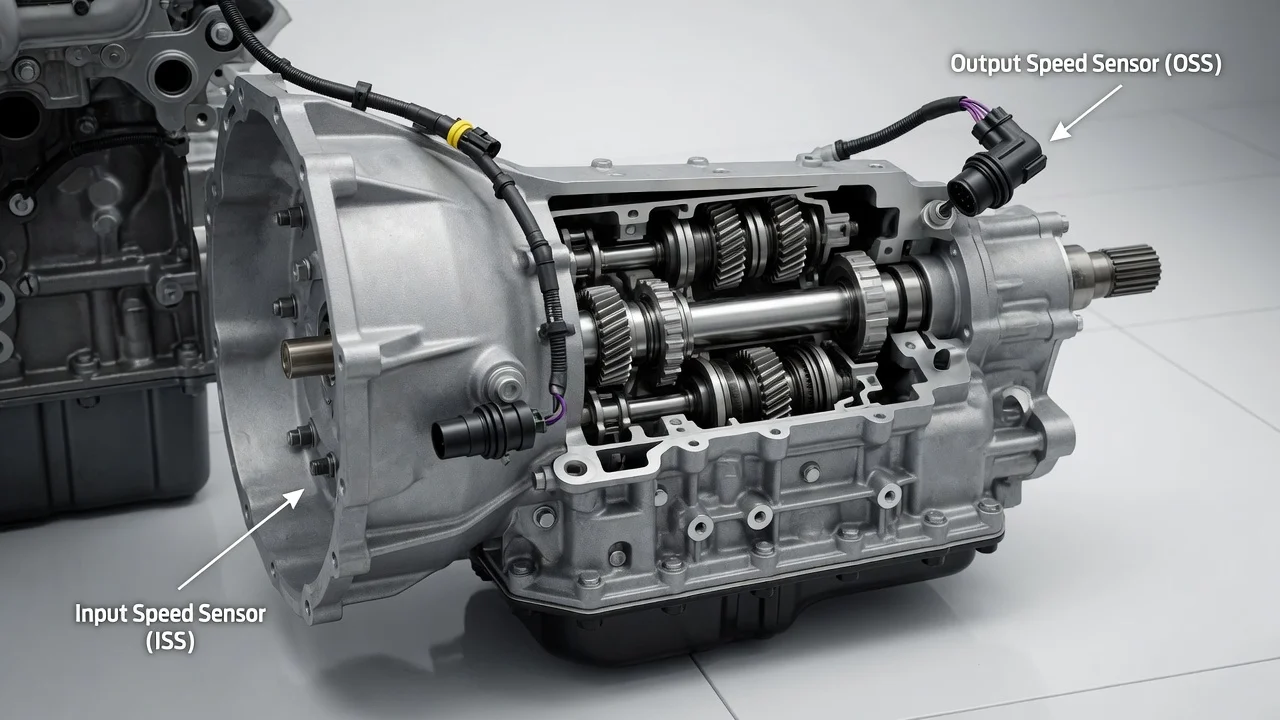
Ford has fitted many different automatic and manual transmissions to its cars, trucks and SUVs, so there is no single location for the transmission speed sensor. Most Ford automatics carry more than one: an input or turbine speed sensor and an output speed sensor, and some designs add an intermediate sensor. This guide explains where these sensors are usually mounted, how to confirm your transmission type, and what a speed sensor code does and does not prove.
Where Ford transmission speed sensors are usually found
On most Ford automatic transmissions with external sensors, the output speed sensor sits toward the rear of the unit, on the case or extension housing near the output shaft, and is reached from underneath the vehicle. The input or turbine speed sensor is usually mounted on the side or top of the case, closer to the bellhousing, where it can read a part that turns with the torque converter turbine. An external sensor is typically a small plastic-bodied unit with a wiring connector, held by a single bolt and sealed with an O-ring.
Treat that description as a starting point, not a guarantee. On several newer Ford designs, some or all speed sensors are internal, mounted to or integrated with the valve body or control assembly, and cannot be seen from outside. On many later models, the speed shown on the speedometer comes from the anti-lock brake wheel speed sensors rather than a dedicated transmission sensor. The exact location depends on the specific transmission fitted to your vehicle.
How transmission speed sensors work
Each sensor faces a toothed wheel, sometimes called a tone wheel or reluctor, on a rotating part inside the transmission. As the teeth pass the sensor tip, it produces a signal whose frequency rises with rotating speed. Older two-wire sensors are usually magnetic pickups that generate their own alternating voltage. Three-wire sensors are typically Hall-effect types that receive a supply voltage and switch a digital signal on and off.
The powertrain or transmission control module compares input speed with output speed to calculate the actual gear ratio and detect clutch slip. It uses that information to time shifts, adjust line pressure and control torque converter clutch lockup, and on some vehicles to feed the speedometer and cruise control. When a signal drops out or becomes implausible, the module may set a fault code, command harsh or erratic shifts, or hold the transmission in a fixed fail-safe gear.
How transmission layout changes the location
Rear-wheel-drive and four-wheel-drive Ford trucks, SUVs and performance cars use longitudinal transmissions. On these, an external output speed sensor is generally found near the rear of the case or on the extension housing. On four-wheel-drive models, the transfer case may carry its own speed sensor, and owners sometimes mistake it for the transmission sensor. Check which housing the part is actually threaded or bolted into before ordering anything.
Front-wheel-drive and many all-wheel-drive Fords use a transverse transaxle mounted beside the engine. Here the input and output sensors are usually on the transaxle case and can sit fairly close together. Reaching them may require removing the air intake ducting, the air filter housing or the battery tray from above, or working from below after removing a splash shield. Older Ford manual transmissions commonly mounted a vehicle speed sensor on the case or extension housing, sometimes in the same bore once used by a mechanical speedometer drive.
Other details that affect the answer
Model year, engine, and drivetrain all matter, because the same Ford nameplate has used different transmissions over its production run, and sometimes more than one in the same model year. A sensor position that fits one generation may not apply to the next. Fitment also changes with sensor design: a two-wire and a three-wire sensor are not interchangeable even if they look similar.
Internal sensor designs are the biggest exception. When a sensor is part of the valve body, an internal wiring frame or a combined control assembly, servicing it may involve draining fluid, removing the pan and working inside the transmission. Some integrated assemblies also require the control module to be programmed or calibrated after replacement, which changes the repair options available to a home mechanic.
How to find and check the sensor on your Ford
Start by identifying the exact transmission type. The certification label on the driver door jamb usually includes a transmission code, a VIN-based parts lookup can confirm it, and service history records may list the unit or past repairs. Many Ford transmissions also carry an identification tag on the case. The same identification determines the correct fluid specification, which matters if any fluid is lost while the sensor is out.
With the vehicle secured on stands on level ground and the exhaust cool, trace the harness from the transmission connector to locate external sensors. Inspect connectors for corrosion, broken locking tabs, fluid inside the plug and wiring chafed against brackets or melted near the exhaust. A scan tool that shows live data lets you compare input and output speed readings during a test drive with a helper, and read stored diagnostic codes such as P0715 for the input or turbine speed sensor circuit, P0720 for the output speed sensor circuit or P0500 for vehicle speed sensor faults.
If an external sensor is removed, expect some fluid to escape, use a new O-ring and follow the specified bolt torque. A light film of metallic fuzz on a magnetic tip is common, but heavy debris can point to internal wear worth investigating. Many newer Ford transmissions have no conventional dipstick, so the fluid level may need to be checked through a fill or check plug at a specified temperature.
Limits of a general guide and when to get help
A speed sensor code indicates a problem with a signal or circuit, not a confirmed failed sensor. Damaged wiring, a loose connector, a damaged tone wheel, low fluid, a control module fault or an internal mechanical problem can produce the same code or the same change in shift behavior. Replacing the sensor without testing the circuit can leave the real cause untouched.
Use vehicle-specific service information for your exact model, year and transmission before starting work, since procedures, torque values and fluid specifications differ. Professional help is sensible when the sensors are internal, when module programming may be needed, when codes return after a sensor has been replaced, or when shifting problems continue with good sensor readings. Bring your service history and any stored codes, which helps a transmission shop narrow the diagnosis faster.