Ford F-150 Transfer Case Shift Motor Wiring Diagram Explained
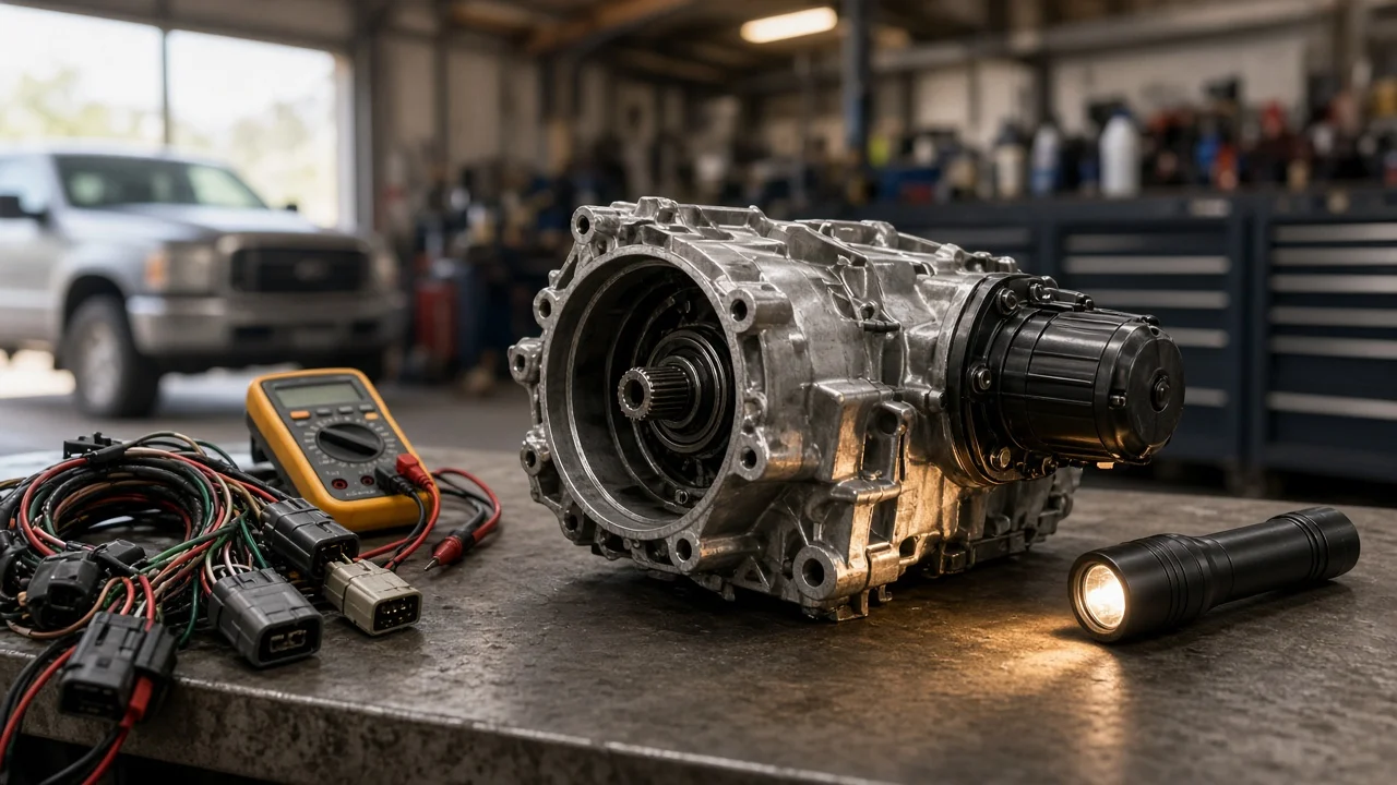
No single wiring diagram fits every Ford F-150 with electronic shift-on-the-fly four-wheel drive. Over the generations, Ford changed the control module, connector layout, wire colors and the way the shift motor reports its position. The basic layout has stayed the same: a reversible 12-volt motor, a position sensor built into the motor assembly, and a control module that drives the motor and reads the sensor. This guide explains that layout and how to test it safely.
The short answer for most F-150 trucks
It helps to read the shift motor wiring as two groups of circuits. The first group is the motor drive pair, the two wires that carry current from the control module to the motor. The module turns the motor one way by putting battery voltage on one wire and ground on the other, then swaps them to turn it back. Neither wire is a permanent feed or a permanent ground. That is why a test light on a single terminal can mislead you. The second group is the position sensor, or encoder, circuits. These tell the module whether the transfer case is in 2H, 4H, 4L or, on trucks that have it, 4A, so the module knows when to stop the motor.
Pin numbers, wire colors and connector shapes depend on the model year, transfer case and module. Use any generic description, including this one, as a map of what each circuit does. Before you cut, splice or back-probe anything, confirm the actual circuits against the factory wiring diagram for your truck's VIN.
How the shift motor circuit works
When you turn or press the 4WD selector, the switch sends a request to the control module. The module first checks operating conditions. For example, a shift into low range usually requires the truck to be stopped or barely moving with the transmission in neutral. The exact requirements are listed in the owner's manual. If the conditions are met, the module powers the motor through its internal drivers. The motor rotates a shaft inside the transfer case, and that shaft moves the internal shift mechanism into the new range or mode.
As the motor turns, the encoder signal changes. Older designs use a contact plate with sliding contacts that connect the sensor circuits to a common ground in a different combination for each position. The module watches this pattern and cuts motor current once the requested position is reached. If the pattern never arrives, or it shows a combination that should be impossible, the module usually stops trying, stores a diagnostic trouble code and may flash the 4x4 indicator. Engaging four-wheel drive also involves the front axle. Depending on the truck, that means vacuum-controlled or electric hub and axle engagement, and some transfer cases also use an electromagnetic clutch to bring the front driveline up to speed. Those components run on separate circuits, often on the same diagram page. They are a common source of confusion when a truck shifts but the front wheels never drive.
What changes the diagram from truck to truck
Model year and generation matter most. In some generations the shift logic lived in a general-purpose body module. Others use a dedicated four-wheel-drive or transfer case control module that communicates over the vehicle network. Pinouts, wire colors and the number of encoder circuits changed along with the module. The selector type also matters: rotary dial, push buttons, or a system with an automatic 4A mode. A truck with a floor-mounted manual transfer case lever has no shift motor at all.
Powertrain type matters as well. The all-electric F-150 Lightning has no conventional transfer case, so this diagram does not apply to it. On a PowerBoost hybrid 4x4, the shift motor and its module run on the ordinary 12-volt system powered by the starter battery. The truck also carries a high-voltage traction system, which is identified by orange cabling. Never probe, unplug or route test leads near those components. If a repair brings you close to them, follow Ford's high-voltage disabling procedure or hand the job to a qualified technician.
Operating conditions can change the outcome too. The motor needs adequate system voltage under load. A weak battery or poor charging output can cause the module to refuse or abort a shift. Cold weather thickens the fluid inside the transfer case, which adds load on the motor. A marginal motor or a marginal connection may therefore fail only on cold mornings.
Testing the circuit as an owner
Start with the basics. Make sure the battery is healthy, the battery terminals are clean and tight, and charging output is normal with the engine running. Check the fuses that feed the 4x4 module and shift motor, using the fuse box legend to find them. If you replace a fuse, use the same fuse rating and never a larger one. Then read codes with a scan tool that can reach body and four-wheel-drive modules. A basic engine code reader often cannot see these faults.
Next, inspect the connector at the motor. It sits on the transfer case, where water, salt and heat attack it. Look for green corrosion, broken locking tabs and chafed wires near the crossmember. Park on level ground with the wheels chocked. Back-probe the two motor drive pins and have a helper request a shift while you watch a meter. You should briefly see roughly system voltage, and the polarity should flip depending on which way the motor is commanded. If voltage is present but the motor does not move, suspect the motor or a mechanical bind. If no voltage appears, look upstream at the fuse, the wiring, the selector input and the module. If the reading is clearly lower than at the battery, do a voltage drop test on the feed and ground paths while the motor is under load. Check the encoder wires for continuity to the module and for shorts to ground.
Disconnect the negative battery terminal before you unplug the motor or remove it. Note the transfer case position first, because the service procedure specifies how a replacement motor must line up with the shift shaft. Do not power an installed motor directly with jumper wires. Without the module reading the encoder, the motor can be driven past its intended stop. If the battery goes flat overnight and the 4x4 system also misbehaves, run a parasitic draw test with the 4x4 fuse in and then removed. That shows whether this circuit is involved.
Limitations and next step
This explanation describes the circuit by function. It cannot give pin numbers or colors without the exact year, transfer case and selector type. Probing guessed pins is a common way to damage module drivers. Some faults also look electrical but are not. Worn internal shift parts, a stretched chain or low fluid can stop a shift even when the motor and wiring test good.
If the motor gets correct voltage and the encoder circuits check out but the system still fails, or if the module itself is suspect, a dealer or a shop with Ford-level diagnostic software is the practical next step. Replacement modules may need configuration before they operate the transfer case correctly. On a hybrid, stop and seek professional help whenever the work is not clearly limited to the 12-volt shift motor circuit.