Ford Explorer Transfer Case Shift Motor Identification
Direct answer
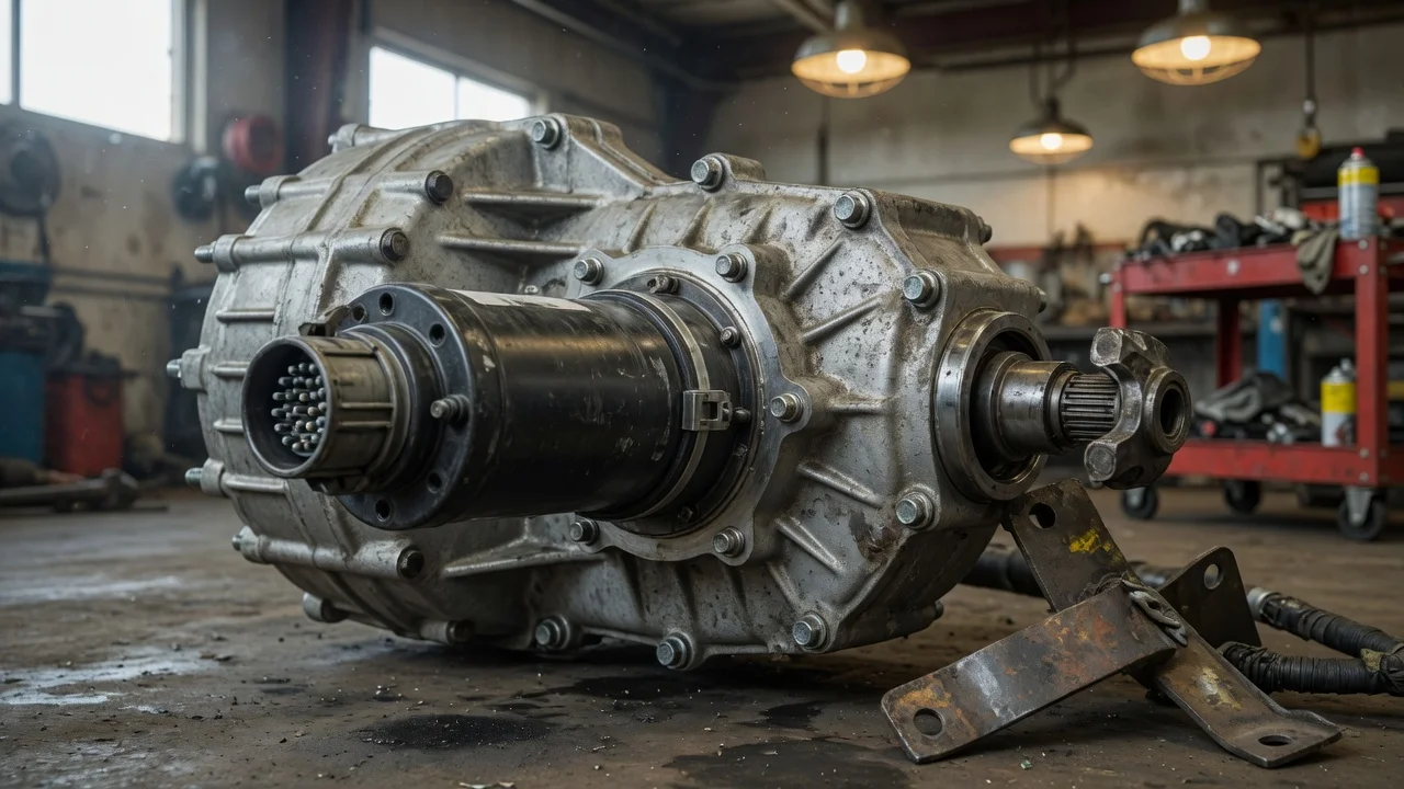
A 2002 Ford Explorer 4x4 transfer case shift motor is an electric motor mounted on the transfer case. Its job is to move the transfer case between ranges and, depending on the system, between two-wheel drive and four-wheel drive modes. The term is often used loosely for the complete motor-and-gear assembly that bolts to the transfer case housing.
There is a model-year complication worth knowing. The 1992 Ford Explorer transfer case shift motor belongs to the earlier electronically shifted BorgWarner 13-54 transfer case design. Later Explorers changed transfer case architecture, so a motor sold for a 1992 model should not be assumed to fit a 2002 model without verifying the exact transfer case and connector. This article focuses on the 2002 application while noting the earlier design where it affects identification.
System context: what the unit actually does
On a 2002 Explorer 4x4, the transfer case shift motor is part of the electronic shift control system. The driver selects a mode, and the control module commands the shift motor to rotate a shift mechanism inside the transfer case. Some versions also need a separate clutch or synchronizer action, but the external motor assembly is the component usually replaced when the system stops changing modes.
Do not confuse the transfer case shift motor with the transmission range sensor, the front axle disconnect actuator, or a wheel-speed sensor. Those are separate components mounted in different locations. The transfer case shift motor is on the transfer case itself, behind the transmission.
How to recognize and locate it
The shift motor is a cylindrical or rounded metal assembly with an electrical connector and mounting fasteners. It is attached to the outside of the transfer case, usually toward the rear or side of the case. On a 2002 Explorer, the transfer case is located behind the transmission and ahead of the rear driveshaft. The motor body may be visible from under the vehicle, but access can be tight because of the crossmember, exhaust routing, and underbody shielding.
The most reliable identification method is to follow the wiring harness to the motor connector. The connector shape and terminal count are model-year specific, so compare the old unit with the replacement before installation. The mounting bolt pattern should also match the transfer case face; a unit from a different transfer case family may look broadly similar but not align.
Likely lookalikes and common confusion
The main lookalike is the shift motor from a different Explorer generation. The 1992–1994 style electronic shift motor is commonly referenced as a Ford Explorer transfer case shift motor, but it is not automatically interchangeable with the 2002 component. Even when the general function is the same, the connector, bolt pattern, internal position sensing, and control logic changed with the transfer case family.
A replacement described only as fitting a Ford Explorer should therefore be treated as unconfirmed. The useful way to narrow the part is by transfer case type, model year, engine, and whether the vehicle has the full-time or part-time four-wheel drive system.
Practical identification steps
Obtain the exact transfer case information for the vehicle rather than relying only on the phrase 4x4. Inspect the existing motor connector and compare its shape and terminal count with the replacement. Check the mounting bolt pattern on the transfer case face. Note the model year and engine because transfer case options can differ within the 2002 model range. Do not assume a 1992-generic shift motor will fit a 2002 Explorer without documented interchange.
Evidence limits
This guide does not provide a universal part number because the correct unit depends on the exact transfer case and vehicle configuration. The supplied reference material does not include a verified engineering diagram or connector pin assignment for the 2002 application, so exact terminal positions should be confirmed against a factory service manual or the existing component. A visual comparison with the removed motor remains the most practical check when documentation is not available.